
7.1 Bending process execution
Basic of the bending process execution in a robot-bending cell
The press brake contains an upper tool called the punch and lower tool called the die between which the sheet metal is placed.
Bending is performed by a press brake machine that can be automatically or manually loaded. Press brakes are available in a variety of different sizes and lengths (20-200 tons) depending on the process requirements.
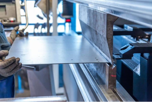
Bending is a process whereby a force is applied to sheet metal which causes it to bend at an angle and form the desired shape. Bends can be short or long depending on what the design requires. The sheet is placed between the two and held in place by the backstop. The bend angle is determined by the depth that the punch forces the sheet into the die. This depth is precisely controlled to achieve the required bend.
Main characteristics in the bending process
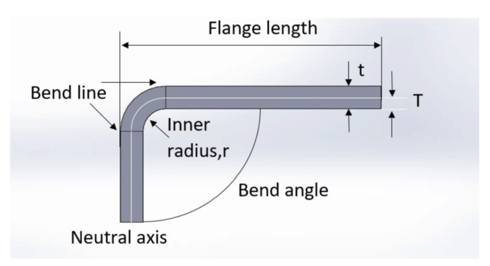
Bend line– The straight line on the surface of the sheet, on either side of the bend, that defines he end of the level flange and the start of the bend.
Bend radius – The distance from the bend axis to the inside surface of the material, between the bend lines.
Bend angle – The angle of the bend, measured between the bent flange and its original position, or as the included angle between perpendicular lines drawn from the bend lines. Sometimes specified as the inside bend radius. The outside bend radius is equal to the inside bend radius plus the sheet thickness.
Neutral axis – The location in the sheet that is neither stretched nor compressed, and therefore remains at a constant length.
K-factor – The location of the neutral axis in the material, calculated as the ratio of the distance of the neutral axis T, to the material thickness t. The K-factor is dependent upon several factors (material, bending operation, bend angle, etc.) and is greater than 0.25, but cannot exceed 0.50. K factor = T/t
Bend allowance – The length of the neutral axis between the bend lines or the arc length of the bend. The bend allowance added to the flange lengths is equal to the total flat length.
The K-factor is the ratio between the the neutral axis to the thickness of the material.

Importance of the K-factor in sheet metal design
The K-factor is used to calculate flat patterns because it is related to how much material is stretched during bending. Therefore it is important to have the value correct in CAD software. The value of the K-factor should range between 0 – 0,5. To be more exact the K-factor can be calculated taking the average of 3 samples from bent parts and plugging the measurements of bend allowance, bend angle, material thickness and inner radius into the following formula:

In sheet metal bending, a flat part is bent using a set of punches and dies. The punch and the die are mounted on a press-brake, which controls the relative motion between the punch and tie, and provides the necessary bending pressure.
Sheet metal bending process consists from the following stages:
- Position 1: part on the die
- Position 2: punch on the part
- Position 3: perform bending
- Position 4: take out the part
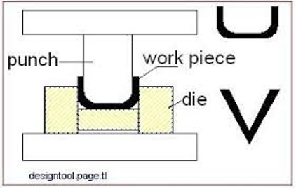
A press brake is a machine tool for bending sheet and plate material, most commonly sheet metal. It forms predetermined bends by clamping the workpiece between a matching punch and die.- Wikipedia
Bending process illustration: www.machinemfg.com
5.2 Bending methods
See the description of the technology of bending methods
BEND WORKS
The Fine Art of Sheet Metal Bending
Olaf Diegel, Complete Design Services
Bottom bending
Bottom bending is one of the types of air bending. In the case of air bending, there is an air gap between the part and the die. Bottom bending is one of the most widely used types of bending, as it allows high-quality and precise bending with relatively low bending force.
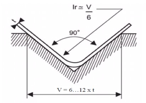
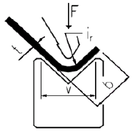
Bottom bending: t – material thickness, V – groove width, ir – inside radius of bending
The suitable width of the V-groove of the die depends on the thickness of the material to be bent. There is a clear relationship between the ratio of V-groove width and material thickness. As the thickness of the material increases, it is necessary to use matrices with a larger V-groove width. Be aware that the width of the edge to be bent and the internal radius of the bend must also be take into account when selecting a suitable die.
Relationship between V-groove width and material thickness
| Material thickness | 0.5-2.6 mm | 3.0 – 8 mm | 9-10 mm | 12 mm või enam |
| V-groove width | 6t | 8t | 10t | 12t |
It has been found experimentally that of the bottom bending the internal radius of the bend is about 1/6 of the width of the V-groove, i.e. ir = V/6. For example, if the width of the V-groove used is six times the thickness of the material, then the inner radius of the bend is the thickness of the material (ir = t). If V = 12t, then ir = 2t.
From these examples, it can be concluded that the internal radius of the bend varies between 1t and 2t. The inside radius of the bend, which is equal to the thickness of the material, is called the standard inside radius. Most bends are made with a standard internal radius ir. The angular accuracy of the bottom bending is affected by the retraction. The most common countermeasure to avoid this problem is to perform a bending equal to the amount of the return. This is why dies for 90-degree bends are available with 90°, 88°, 85° and 80° V-groove angles. 90-degree dies do not have a margin for retraction. Angles of 90° are achievable by applying a bending force at which the ratio of negative to positive retractions gives the desired result.
The vertex angle of the stamp used for bottom bending and the angle of the V-groove must be the same value. This is the main prerequisite for achieving the desired bending result with precision.
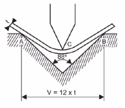
Partial bending
The name partial bending is due to the fact that the detail partly concerns the tools. There are three contact points (points A, B and C). Partial bending is a typical air bending characterized by a wide range of achievable bending angles. For example, by using a stamp and die with an angle of 30 degrees, it is possible to achieve angles between 30 and 180 degrees. Partial bending is convenient to use and is therefore widely used in addition to bottom bending. Based on partial bending, the width of the V-groove of the die must be 12 to 15 times the thickness of the material to achieve the required accuracy.
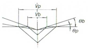
In the figure on the right, the width of the V-groove used for bottom bending is Vb and the width of the V-groove used for partial bending is Vp; Vp is almost twice as large as Vb. If the penetration depth of the stamp die is the same in both cases, then the bending angle θp is small compared to the angle θb. This means that the variation of the bending angle is smaller for Vp compared to Vb.
By using a die with a wider V-groove than that used for bottom bending in the case of partial bending, a sufficiently good accuracy can be achieved. However, even with a wider die, the accuracy of partial bending is lower than that achieved with bottom bending. Therefore, it is recommended to use bottom deflection if high accuracy is important.
Coining
It may seem strange that the bending method is called coining. The concept of coining derives from the production of coins. Despite the production of large series, there must be no differences in the size of the coins. Therefore, this name is also applied to this bending method, as it allows precise bends to be achieved. Coining has two major advantages: (1) very high bending accuracy and (2) the ability to reduce the size of the internal radius to as small as the material properties allow. The figure below shows the position of the part and tools in the final phase of coining, where it can be seen that the tip of the stamp has penetrated in the material.
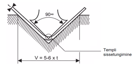
Penetration of the stamp the high pressure exerted by the material and the V-groove of the stamp and die eliminates back-springing. This is why coining requires 5 to 8 times more bending force. The width of the V-groove is smaller when using coining than with bottom bending, preferably 5 times the thickness of the material.
One goal is to reduce the internal radius of the bend, which in turn reduces the depth of penetration of the stamp material. The contact area of the V-groove of the smaller die is smaller and therefore the contact loads during bending are higher because the bending force is distributed over a smaller area. Higher pressure per unit area helps to eliminate back-springing more effectively. It is important to remember that the large width of the V-groove has an impeding effect on the coining process.
When coining, the angle between the stamp and the die must be equal to the desired bending angle. For example, a 90-degree stamp and die must be used to make a 90-degree bend. It is not necessary to take into account the back-springing. As mentioned earlier, high bending forces are required for coining. The maximum thickness of the material to be coining depends on the tonnage of the bending press and is also limited by the maximum allowable force that the upper beam can withstand.
When coining 1.6 mm thick cold rolled low carbon steel, a force of 75 tones per meter is required and for 2 mm cold rolled low carbon steel approximately 115 tones per meter. Thus, the maximum thickness of the bending material is up to 2 mm, as most bending presses have a permissible load on the upper beam of 100 tons per meter
5.3 Basics of bending method selection
The choice of bending method must take into account the scope of the product and the functional requirements for it. When using NC bending presses, sharp tools allow both obtuse and acute bends by partial bending. If the product does not require high accuracy, then it is a universal and inexpensive method. Requirements for accuracy have been increasing for certain products. Therefore, in some cases, precision is required, which is only possible with coining. The use of coining is likely to achieve a significantly higher bearing surface in the future.
As noted earlier, bottom bending is the most commonly used method because of its relatively high accuracy. Bottom bending is also a sustainable production method and is therefore likely to play an important role in the future. An important problem with bottom deflection is back-springing. At the same time, there is a lot of information about back-springing that has been used successfully in the design of tools. The measures used back-springing are now effective enough to use the bottom deflection easily and without problems.
Feasibility of using bending methods
| Bending method | V-groove width | ir | Bending angle accuracy | Surface accuracy | Comments |
| Partial bending | 12t-15t | 2t-2,5t | ± 45‘ | Large bending radius is created | The range of bending angles is freely selectable |
| Bottom bending | 6t-12t | 1t-2t | ± 30‘ | Good | Good accuracy can beachieved with relatively low tonnage |
| Coining | 5t | 0,5t-0,8t | ± 15‘ | Good | Very high accuracy. The required tonnage is 5 to 8 times higher than the bottom bending |
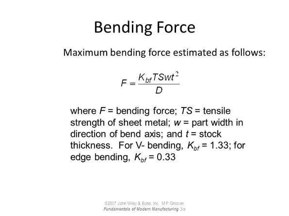
5.4 Bending force and its calculatio
Bending force is the amount of energy it takes to compromise the item from its natural shape or condition. A bending force is a combination of tension and compression. In bending operations, bottom bending is used frequently at the bottom dead centre in order to stabilize the shape.
V-Bending force calculation
www.custompartnet.com/calculator/v-bending-force
Calculation of sheet metal bending force in air bending: www.machinemfg.com/calculation-of-sheet-metal-bending-force-in-air-bending/
Determination of bending force
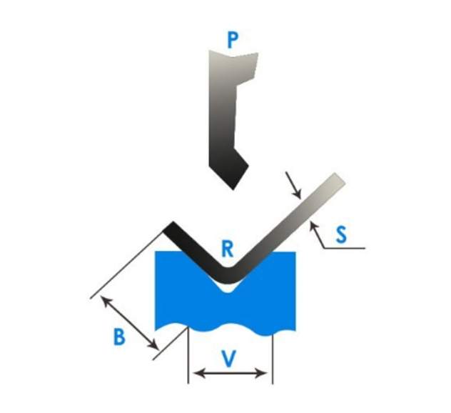
The required bending force F must be found by the following steps. First, select the width of the die V-groove of the bending according to the thickness t of the material to be bent. Then move along the row corresponding to the selected thickness t to the right until it intersects the column corresponding to the selected die V. For example, if a 12 mm V-groove die is used to bend 2 mm of material, the bending force F found in the table is 22 tons. In reality, the bendable edges are of different lengths and materials with different tensile strengths are given in the table. The table is still usable. The nature of the parameters used in the bending table is shown in Figure.
Designations for bending force calculation: t – material thickness; F- applied force; v-groove width; b– minimum width of the bendable edge
The width of the V-groove can be found based on the thickness of the material. Depending on the width of the selected V-groove, the minimum width of the bending edge can be found. Here’s why edge width has a minimum value. Throughout the bending operation, the material must be firmly supported by the edges of the V-die. If the support is not guaranteed, the part may slip off the edge of the die and the exact bending result is not guaranteed, and the bending process becomes dangerous. The minimum edge requirement must be complied with to ensure sufficient accuracy and safety. The minimum edge width is calculated by the formula:
- b – minimum edge width
- V – width of the V-groove of the die
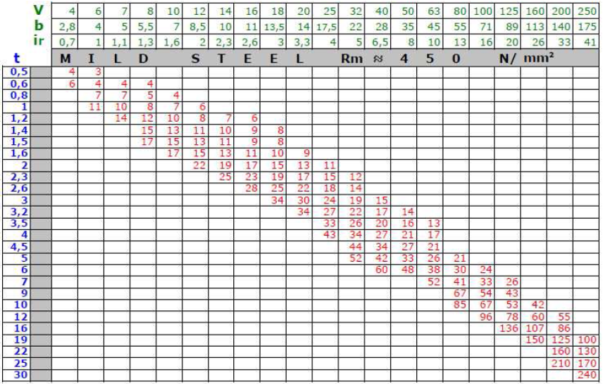
The table shows the required bending force for bending a 1 m long low-carbon steel part with a tensile strength of 450… 500 N/mm². The forces shown in the table apply to bottom bending (as a rule for most bending tables).
Example
The following is a calculation example: How much bending force is required to bend a 1.5 mm thick and 4 m long stainless steel detail (tensile strength 600 N/mm²)?
Solution: A suitable V-groove width is V = 6 x 1.5-> 10 (6 x 1.5 = 9, but the standard tool of the following size is V = 10 mm). Based on the thickness of the material and the width of the V-groove, the force required to bend low carbon steel, which is 15 tons, can be found. As stainless steel is stronger, it is calculated in the following computer formula: F = 15 x 60/45 x 4 = 80 tons.
5.5 Relationship between bending angle and required bending force
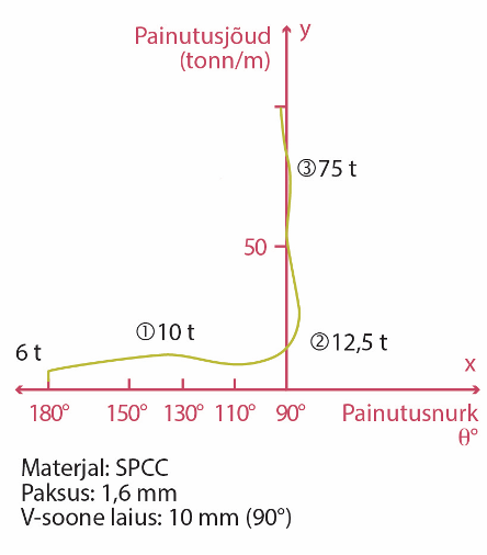
If a smooth sheet is crushed with a die and stamp installed on a bending machine, it will start to bend depending on the amount of force applied. Based on the force of the bending process and the corresponding bending angles, a graph can be drawn. The shape of the resulting curve, also called the S-curve due to its similarity to the letter S, varies significantly for different types of materials. Figure 3.94 shows the bending curve of cold rolled low carbon steel (SPCC). The force required to bend a 1 m long detail is applied to the Y axis and the bending angle θ corresponding to the force is applied to the X axis. Bending angle θ means the angle reached after removal of the force.
- Material: SPCC
- Thickness: 1,6 mm
- V-groove width: 10 mm (90⁰)
- Bending force (tonn/mm)
- Bending angle
The sheet placed between the die and the stamp will not bend immediately after the force is applied, the bending force must reach a certain level before. Figure 3.94 shows a sharp increase in bending force (vertical part of the curve). The sheet begins to bend slightly at a load of about 6 tons, but the deflection disappears when the force is removed. This is due to the elasticity of the material. Elasticity is the property of a material to restore its former dimensions after the cessation of force. At the beginning of the bending process, the force increases slightly and reaches its maximum value (10 tons) when the bending angle of 130 degrees is reached. If you continue to bend, the bending force will start to decrease slightly.
As can be seen from the graph, small changes in the bending force in this area cause abrupt changes in the bending angle (the area is indicated by the number 1 in the graph). The required bending force starts to increase again when the bending angle decreases below 10 degrees. The force required to achieve a 90-degree bend is about 12.5 tons, which is 25% higher than with a 130-degree bend.
The force that bends the sheet at a 90-degree angle is called the required tonnage of the material. If you continue to bend the material, the angle will decrease by 3… 4 degrees to less than 90-degrees and an acute angle will be reached. This is shown in the graph as area 2.
As the bending force further increases, the acute angle becomes a 90-degree angle again. The force required to achieve this is approximately 75 tons, which is almost 6 times the required tonnage. The sharp rise of the curve shown in the figure along the Y-axis at an angle of 90- degrees characterizes the rapid increase in the bending force. The area where the change in bending angle is small despite the increase in force is indicated by the number 3 on the graph. The events in areas 1, 2 and 3 are called respectively partial bending, bottom bending and coining. These bending processes are three types of bending. Partial deflection and bottom deflection are collectively referred to as air deflection.
5.6 Bending angle back-springing
Back-springing plays an important role in the bending process. The figure below illustrates the V-bending back-springing by which the obtuse angle, right angle or acute angle changes after removal of the force. In the figure, the solid line indicates the angle (θ’) achieved during the bending process, and the dashed line indicates the angle (θ) that the product acquires after the force is removed.
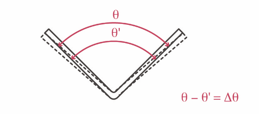
Bending retraction
The nature of the back-springing is discussed below from two perspectives. In one case, the back-springing is explained on the basis of a tension stretching diagram, and in another case, the relocation of the molecules inside details.
The tension diagram below shows how the deformation decreases sharply when the external force is reduced by a small value at point G. The decrease occurs parallel to line 0A (this is the elastic range – stretching is proportional to the tension). When the force is removed from the detail, the deformation of the detail is indicated by point X. This indicates that the material also has elasticity in the plastic area. In the graph, section G’X shows the value by which the dimensions of the detail change after the force is removed, section 0X shows the permanent deformation.
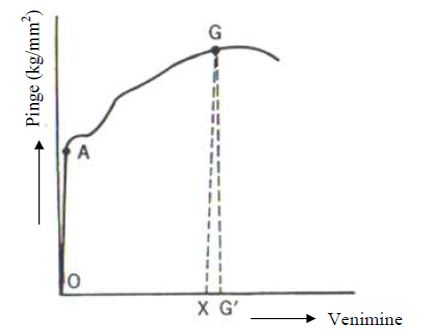
The conclusion of the above discussion is that the elasticity of the material is not eliminated even when the tension in the material exceed the yield strength. This fact is the reason for the back-springing.
The figure below is an amplified illustration of the displacement of molecules in a smooth sheet when bent at an obtuse angle or 90⁰ degrees.
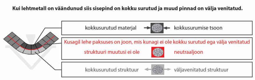
Compression and stretching of the material structure at the place of bending
The inner side of the detail is compressed and the outer side is stretched. There is a plane in the middle of the inside and outside that is not compressed or stretched. This is called a neutral plane or neutral line. When the detail is bent, opposite loads are created, which are located on the both side of the neutral line.
In general, the compressive strength of the material is significantly higher than the tensile strength. The bending force causes a permanent deformation on the outside of the part, but for the inside, the same force does not create tension exceeding the flow limit. Therefore, the inner side is trying to restore its former shape. This causes it to back-springing.