Robotics general principles
Smart manufacturing is integrating networked-based data and information that comprises the real-time understanding, reasoning, planning and management of all aspects of a manufacturing and supply chain enterprise. SM is faciliated through use of advanced sensor-based data analytics, modelling and simulation in real-time. SM is manufacturing in which all information is avaiable when it is needed, where it is needed and in the form it is most useful-infusing manufacturing intelligence throughout the lifecycle of design, engineering, planning and production [SMLC- Smart Manufacturing Leadership Coalition]
The main manufacturing paradigms and these objectives are described in [28]. The needs for reconfigurability and the ability to produce smaller lot sizes of personalised products require not only smart mechatronics but also higher efficiency and effectiveness in the planning and engineering of such manufacturing systems.
In order to achieve a wide and successful implementation and decision making capabilities for these smart and autonomous robots interacting with other robots, with machinery and with human workers as well as distributed embedded real time systems should be investigated, with capability to analyse large volumes of sensory data.
In order to achieve a wide and successful implementation of innovative robotics solution in manufacturing environments, in particular in SME-s, trialling and validation activities are required. These activities will perform system integration of intelligent robotics functions and solution resulting from more upstream research in industrially relevant manufacturing environments.
The research priorities are: advanced manufacturing processes, adaptive and smart manufacturing systems; human-centred manufacturing and customer focused manufacturing; human-oriented interfaces for workers: process-oriented simulation and visualisation. [29]
Modular self-reconfigurable robots (MRSs) are systems which rely on modularity for maneuvering over unstructured terrains, while having the ability to complete multiple assigned function in a distributed way. An MSR should be equipped with robust and efficient docking interfaces to ensure enhanced autonomy and self-reconfiguration ability.[30]
The main field of application for robots today is mass and batch production. [31]. But the developments are for manufacturing with lot size 1. The main goal is to have a real SME-robot, what is cost-effective, flexible and adaptable for small lot size production. Because of small lot sizes, fast adaptability of robot and surrounding cell to new products and processes is much more important for SME-s than short cycle times [32].
One pillar in the new approach to manufacturing is a dynamic, reconfigurable production system, a fully-integrated, collaborative manufacturing system which responds in real time to meet changing demands and conditions in the factory, in the supply network, and in meeting customer needs. Robot systems that must perform well over increasing uncertainty ranges. There is also necessary to develop self-monitoring and self-healing capabilities of robot-based work-cells.
Robot-cell description
A robot based manufacturing cell (system) we can consider as a closed system within some large unit (workshop). The system can be described with the help of dimensioning its main parts, giving the relationships between them and forming the structure of the system. Formal description of a robotized manufacturing system is the following. The system consists of m machine tools or other equipment (MT)
MT = { MTi │i = 1,2,..., m}
and n industrial robots (IR)
IR = { IRj │ j = 1,2, ..., n},
which could have four kinds of possible relations: {1:1},{1:m},{n:1}, {n:m}. In the system there is usually also a number k of buffers {BF} with a fixed number of places on them
BF = {BFl │ l = 1, 2, ..., k}.
They can be connected with the machine tools {1:1} or {1:m} or with industrial robots {1:1} or {1:n} if there is for example one buffer.
To the primary, so called formal description, it follows more detailed system characteristics representation. These characteristics, which are expressed through the workpiece loading- unloading time, gripper (end effector) changing time, IR working area range, loading capacity, controlled coordinates of IR and MT, etc are obtained from the corresponding data files directly or using some mathematical variations. So, additionally to the system general model, the time relations and system parts numerical models are in use to carry out the planning process. That kind of model is suitable for all robor-based manufacturing systems: machining, assembly, welding, loading, etc. On the basis of this general description, it is possible to develop a set of robot-based manufacturing systems as an use-cases with corresponding manufacturing and planning information. This could be used as expert advice in decision making process.
The decision making problems have been treated individually, consistency is not kept between the decision making functions regarding to the assumptions and data structures. These isolated decision making stages (see Fig. 3. ) do not help to achieve the global optimum solution because the decision making problems in manufacturing involve very complex data processing. The elementary estimations are very strongly depended of each other and the real technological resources (capabilities) must be taken into consideration. Therefore the rational decisions usually can not be made simply with sequential procedures (see Fig. 3). However with modelling and simulation procedures there is possile to analyse the alternatives and find the best solution. The other possibility is starting from the complex systems theory and to develop a solution system architecture, allowing reduction of compexity of a designing process, minimizing risks in production system planning and enabling analysis of various production variants (see Fig.5.11)[33].
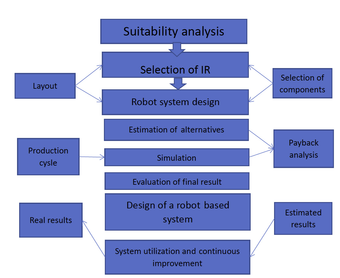
Figure 5.1 Stages of robotisation
The whole planning system is based on the hierarchical decision- making scheme. Nodes on it represent the decision centres. On these centres the elementary estimations are carried out. These elementary decision- making procedures are carried out on the bases of different mathematical methods and systems. These elementary decisions could not be in conflict with each other. For this purpose there are coordination levels, which take care of the elementary decisions, analysis these and gives the rules for further activities. That means that modelling and optimization techniques are integrated with the expert system. The basic components of the system planning architecture are: data storage, decision making mechanism, knowledge base and interpreter. Last on each the following main activities: to call out the needed solution module, to analyse the obtained results, to generate the rules and instructions on the existence of contradictions, to issue the sorting and searching commands to the database. Through the interpreter the recycling of the solving problem is possible.
A modular architecture qives the flexibility of the planning system. The result would be obtained on the bases of different modules and models. The order of use of these moduls must not be directly determined. That kind of flexibility gives to the users the extensive possibilities to teach the most suitable goal.
5.3. Robot cell design process
Input information: product nomenclature, batch sizes, annual programme, workpiece technical data
- Design process
- Location in a workshop and communications
- Integration needs
- Process description
- Layout alternatives
- IR selection (selection principles)
- Alternatives estimation
- End-effectors (commercial, own design)
- Layout presentation
- Needed fixtures (commercial, own design)
- Estimated processing time (cycle time)
- Cost calculations and pay-back calculations
5.4. Layout design principles
Layout have a big importance to the productivity and flexibility of a production system. Flexibility is a ability to perform quick changeover of operating instructions or physical set-up. Flexibility has the following capabilities (part variety, schedule changeover, error recovery, new part introducing). Productivity as it is understood in terms of its output with respect to its capital input (pc per hour, etc) is in practice usually insufficient. Productivity may not be the manufacturing performance criterion (KPI are sufficient), which is most closely associated with the competitive focus of the system.
Robot-based production system 3D layout is presented in the Fig 5.2.
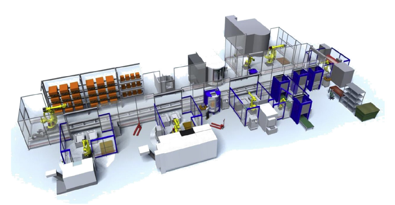
Figure 5.2. 3D model of a robot-based manufacturing system.
Layout strategy specifies the arrangement of processes, the related equipment and work areas, including servicing and storage areas; facilities the flow of materials and people within and between areas.
Objective is to develop an economic layout that will meet the requirements of:
- Product specification and volume
- Process equipment and capacity
- Quality of work
- Building and site constraints
The criteria of a good layout are:
Maximum flexibility
2. Maximum integration
3. Maximum use of volume
4. Maximum visibility
5. Maximum accessability
6. Minimum distance
7. Minimum handling
8. Minimum disconfort
9. Maximum security
10. Efficient process flow
Advantages of a good layout are:
-
- The overall process time and cost will be minimized by reducing unnecessary handling and movement
- Total output from a given facility will be as high as possible by making the maximum effective use of avaiable space and resources
- Quality of the products or service will be sustained by safer and more effective methods of operation
- Supervision and control will be simplified by the elimination of “hidden corners”
Designing the layout the most important is minimizing the costs of movements, optimization the “spagetty” diagram.
Minimize Cost
Min ∑ X ij x Cij
Where .n – total number of departments or workplaces
i,j – individual equipments or workplaces
X - number of loads moved from workplace i to j (machine tool i to machine tool j)
C - cost to move a load from place i to j
- Main input parameters to the layout design
- Specification of objects of the system in terms of output and flexibility
- Estimation of product or service demand on the system
- Processing requirements in terms of number of operations and amount of flow between departments and workplaces
- Space requirements of the elements in the layout
- Space avaiability within the facility itself
References
[28] Mehrabi,M.,G., Uslov A.G., Koren Y. Reconfigurable manufacturing systems: Key to future manufacturing. Jpurnal of Intelligent Manufacturing, 11, 2000, pp 403-419
[29] Factories of the Future Multi-annual roadmap for the conceptual PPP under Horizon 2020. EU Commission, 2013
[30] Hossain,S.G.M., Nelson Carl A., Chu, K.D. Dasqupta P. Kinematics and Interfacing of ModRED: A Self-Healing Capable, 4DOF Modular Self-Reconfigurable Robot. Journal of Mechanisms and Robotics 6 (4), Aug, 2014
[31] http://www.ifr.org/industrial-robots/statistics/
[32] Naumann, M., Wegener, K., Schraft R.D., Control Architecture for Robot Cells to Enable Plug`n Produce. IEEE International Conference on Robotics and Automation. Roma, Italy, April 2007
[33] Kangru, T.; Riives, J.; Otto, T.; Kuts, V.; Moor, M. (2020). Optimisation of decision-making process in industrial robot selection. Journal of Machine Engineering, 20 (1), 70−81. DOI: 10.36897/jme/117788.