5 Programming robots in the robot bending cell
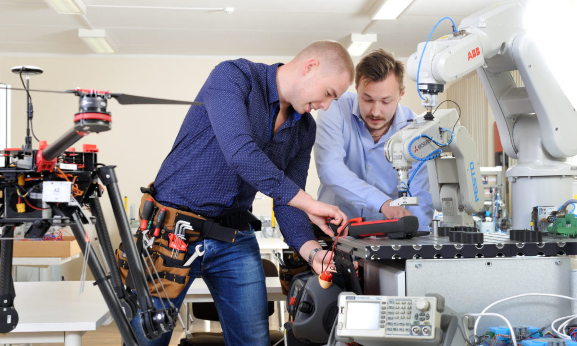
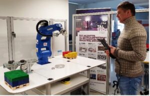
There are two options to program industrial robots (Figure 1):
- On-line – industrial robot is programmed directly with the help of the teach pendant
- Off-line – the program for the robot is made on an PC independently from the actual robot and later it is uploaded to the real industrial robot
 |
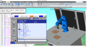 |
Figure 1. Industrial robot on-line (left) and off-line (right) programming
The first option can be implemented when the robot bending cell is not working. In most cases the program creation for the robot is not consistent. It is going to be interrupted when something should be produced with the robot bending cell. This increases the robot programming time a lot and no one can say, when will it be finished (ready to use).
The second option allows to make the programs for robots even when the real robot bending cell is in the use. For that different software’s (text editors, simulators, etc.) can be used. Yaskawa offers JobEditor and MotoSim EG-VRC for programming their industrial robots. Here has to be mentioned, that each robot manufacture offers their own software to program only their robot. Unfortunately, these software’s are not cross usable (to use MotoSim EG-VRC to program a KUKA robot).
The first Yaskawa software is like a text editor (notepad), which allows only to write/edit the robot program (Yaskawa calls a robot program as job). The second one, beside program writing, allows also to test the program on a virtual robot cell (it simulates the cell work). This allows to find mistakes in the program and to optimize the robot motions (get the cell faster working). However, a virtual robot cell has to be built on the computer, which has to match the real robot cell.
Still after the off-line programming the on-line programming has to be used to finalize the robot program on the real robot cell. There may be a need to change/modify the robot program (add additional motions to avoid collisions, reteach the positions when something has been moved, etc.).
There are third part companies who offer software’s for industrial robot programming. Here is a small list of existing software’s:
- MRobot
- OBELISK
- Robot Bender, PartManager
- RobotExpert
- RoboDK
- ArtiMinds RPS
- OCTOPUZ
- Delfoi Robotics
- Robotmaster
- Inropa™ OLP CAD
- FAMOS robotic
- FASTSUITE
This software’s can be used to program ABB, KUKA, FANUC, Yaskawa, etc. industrial robots and to simulate the operation of the robot cells on a computer. They are not focusing on one robot manufacturer.
In the end, it is recommended to ask the robot bending cell vendors what software to use to program the robot bending cell. They may know a software, which allows to program the industrial robot and bending machine together. They also may offer virtual robot bending cell system (correspond to the real robot bending cell), but of course for additional cost.
1 Yaskawa industrial robot programming language
Yaskawa uses programming language called INFROM to program their industrial robots (Figure 2). However, it cannot be used to program other robot manufacturer industrial robots. Each robot manufacture uses their own programming language to program their robots. Here is a small list of existing robot programming languages:
- MELFA-BASEC – Programming language for Mitsubishi robots
- INFROM – Programming language for YASKAWA robots
- RAPID – Programming language for ABB robots
- KUKA Robot Language (KRL) – Programming language for KUKA robots
- TP (TeachPendant) – Simple programming language used in FANUC teach pendant and programming software
- KAREL – More advanced programming language for FANUC robots
- PDL2 – Programming language for Comau robots
- AS – Programming language for Kawasaki robots
- VAL3 – Programming language for Stäubli robots
- URScript – Programming language for Universal Robots
The robot program consists of a series of instruction-lines, which are executed one by one (line by line). Second instruction-line will be executed when the first instruction-line has been executed or the robot has reached the desired point/position.
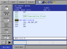
Figure 2. A sample of a program/job written in INFORM
The instructions used in the robot program instruction-lines are divided into sub groups as shown below:
- I/O instruction – instructions used to control the I/O (inputs and outputs) of the robot system
- DOUT – allows to turn the digital general-purpose output signal ON or OFF on the robot controller
- WAIT – robot program execution waits until a given condition (a digital input has been switched ON) has been reached
- PULSE – a pulse signal (signal 1 or 0 for 0.3 sec) is given to a digital general-purpose output
- Control instruction – Instructions used to control the processing and operation
- JUMP – jumps to specified label in a job/program or to a job. Labels are marked with *
- CALL – calls specified job/program, which can be found in the robot controller
- TIMER – robot waiting instruction, which is given in seconds. After the time has elapsed, the robot program execution continues
- *(LABLE) – specifies the label name for the jump instruction. Valid only within the job
- ‘(comment) – specifies the comment in the job. Normally it is used in the beginning of the instruction line. It is limited to 32 characters
- RET – return back to the calling job/program from current job/program
- NOP – caries out no operation. Is used in the beginning of a job
- PAUSE – stops the job/program execution temporally
- Operating instruction – Instructions which operate with variables
- INC – increases a variable value by 1
- DEC – decreases a variable value by 1
- SET – it gives a value or in a variable existing value to another variable
- ADD – sums variable 1 and variable 2 values and saves the result in variable 1
- SUB – subtracts variable 2 from variable 1 and saves the result in variable 1
- CNVRT - converts the pulse type position type variable to a XYZ type position type variable in the specified coordinate system
- SETE – sets some data (value) to a position type variable
- GETS – stores system variable data to a presented variable
- Move instruction – Instructions controlling the robot motion and speed
- MOVJ – moves the robot manipulator to the taught position by joint interpolation. Additionally, the robot manipulator motion speed and position level (approach level to the taught position, when the robot starts to execute next instruction-line) are also defined with the motion instruction
- MOVL – moves the robot manipulator to the taught position by linear interpolation (the end-effector moves straight). Here also the motion speed and position level are defined
- REFP – sets a position data for a reference position
- Shift instruction – Instructions used to shift positions used in motion instructions
- SFTON – activates the position shifting. The shifting value is given by a position variable
- SFTOFF – ends the position shifting
- Instruction which adheres to an instruction – Additional instructions, which can be added to the main instruction
- IF – evaluates some conditions during an instruction execution (like JUMP). It is added after other instructions
- UNTIL – it is added to a motion instruction. If the condition has been met, then the ongoing motion instructions is forcibly completed and next instruction line is executed
- Work instruction – Instructions related to the work (arc welding, handling, etc.) which the robot is doing
- Optional instruction – Instructions concerning optional functions, which have to be bought separately
This allows to find the instruction faster on the teach pendant. Some sample instructions have been explained here. This are used later in sample robot programs (chapter 3), which are controlling an industrial robot in a robot bending cell.
Beside instruction, INFORM has global and local variables. First ones can be used everywhere and they allow to transfer some values or info from one job to another job. They can be used to count program cycles, produced products, length measurement, position data, etc. Here are some global variable samples:
- B000-B099 – byte variable, size 8 bits, and value is from 0 .. 255
- I000-I099 – integer variable, size 16 bits, and value is from -32768 .. +32767
- D000-D099 – double variable, size is 32 bits, and value is from -2147483648 .. 2147483647
- R000-R099 – real variable, size is 32 bits, and value upper limit +/-3.402823e+38 and lover limit +/-1.175495e-38
- P000-P0127 – position variable, which stores the robot arm coordinates as motor pulses or XYZ
- EX000-EX0127 – external axis (station) position variable, which stores the robot’s external axis position value as motor pulses or XYZ
Local variables are used only in the job, where they have been defined. So, a local variable with the same name can be defined in different jobs, but it does not transfer data (value) from one job to another. The L letter is written before other parts of the variable (like LB001). Local position variables are mostly presented by a C letter and position data is given in pulses.
More explanations about INFORM and usage samples of the instructions can be found in a manual called “YRC1000 OPTIONS, INSTRUCTIONSFOR INFORM LANGUAGE”.
2 Sample robot program for a robot bending cell
In this chapter a Yaskawa industrial robot program (usable in a robot bending cell) is presented. For better understating, the program has been divided between different jobs. However, it is possible that the whole program is written in one job and some companies (robot operator/technician) prefer it that way (everything in one place).
2.1 Job: MAIN
This is the main job, from where other jobs, used in the robot bending cell, are called out (Figure 3 and Table 1).
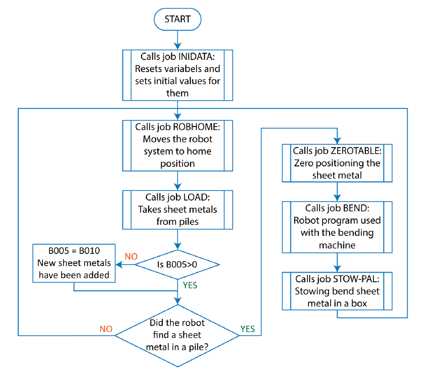
Figure 3. Job MAIN flowchart
As seen in the Table 1 the job starts with some comments (marked with '), which gives information about the job and tasks for the robot operator (what product is bend with the job, which end-effector is used (control it), etc.). There are other comments in the middle of the job. This are used to describe the code by some key words (a comment is limited by 32 characters). Dashed lines are used to separate some job parts, which gives better overview of the jobs structure and makes it more readable.
The robot job starts with calling a job INITDATA (line 7) for initializing data (variables). Variables values are set to 0 and then some initial values are given (ch 3.2). Then job named ROBHOME (line 10) is called, which moves the robot to home position (ch 3.3). Next a job called LOAD (line 13) for finding sheet metals in a pile and gripping them is called and executed (ch 3.5). Then variable B010 value is given to variable B005, if its value was 0 (line 15 and 16). This means, that robot used all piles and now new sheet metal piles have been added on the feeding table.
Table 1. Job MAIN with comments
| Line nr | Instruction line | Comment |
| 0 | NOP | Beginning of the job |
| 1 | 'QV-0123 | Product name or code |
| 2 | 'NB!! Check the 0-table limiters | Additional information for the robot operator |
| 3 | 'END-EFFECTOR XRC TOOL10 | Specifies the end-effector, which is used by the robot |
| 4 | 'EURpal with max materials | Information for the robot operator about a pallet with raw materials (sheet metal) |
| 5 | '------------------------------ | Separation line to structure the robot job |
| 6 | 'Init system | Comment |
| 7 | CALL JOB:INITDATA | Calls job named INITDATA, to reset and give initial values to the variables used in this robot program (in other jobs) |
| 8 | '------------------------------ | |
| 9 | *BEGIN | Label, to where the program will jump |
| 10 | CALL JOB:ROBHOME | Calls job named ROBHOME, to move the robot arm and external axis to home position |
| 11 | '------------------------------ | |
| 12 | 'Taking material from a pile | Comment |
| 13 | CALL JOB:LOAD | Calls job named LOAD, to look and to take materials from piles |
| 14 | '------------------------------ | |
| 15 | JUMP *1 IF B005>0 | Jumps over the next instruction line when B005 value is bigger than 0 |
| 16 | SET B005 B010 | Variable B010 value is given to variable B005 |
| 17 | *1 | Label, to where the program is jumping from line 16 |
| 18 | '------------------------------ | |
| 19 | JUMP *BEGIN IF B002=0 | Jumps to label *BEGIN, if robot did not find any materials in one pile |
| 20 | '------------------------------ | |
| 21 | 'Position material on table | Comment |
| 22 | 'Zero rack | Comment |
| 23 | CALL JOB:ZEROTABLE | Calls job named ZEROTABLE, where the material is zero positioned for the bending process |
| 24 | '------------------------------ | |
| 25 | 'Bending | Comment |
| 26 | 'NB! Insert correct bending job! | Information for the robot operator or technician about bending job of the robot |
| 27 | CALL JOB:BEND | Calls job named BEND, where is written the program to control the robot and bend machine for the bending process |
| 28 | '------------------------------ | |
| 29 | 'Laying stacks | Comment |
| 30 | 'Stowing | Comment |
| 31 | CALL JOB:STOW-PAL | Calles job named STOW-PAL, where the bent sheet metal is placed on a pallet or in a box |
| 32 | '-------------------------------- | |
| 33 | JUMP *BEGIN | Jumps to label *BEGIN, so that a new sheet metal can be bend into the correct shape and stored in a box |
| 34 | END | Marks the job end |
If no materials were found in a pile (the sheet metal was not gripped, line 19) then the robot program execution jumps to line 10, which is marked by a label *BEGIN. With that, the robot will go to the next pile of sheet metals and starts to take them from there. The existing pile control and sheet metal refill is carried out in job LAOD (ch 3.5). The variable B005 is used to store the number of sheet metal piles and the variable B002 is used to show that the robot has gripped a sheet metal (there are sheet metals in the pile).
Then next jobs are carried out one after another:
- ZEROTABLE (line 23) – used to position the sheet metal as needed for the bending process (ch 6). The sheet metals are not positioned correctly as needed (the may be sifted to right/left or forward/backward on the feeding table)
- BEND (line 27) – used to bend the sheet metal by controlling the robot arm motions and bend machine work (ch 7)
- STOW-PAL (line 31) – used to stow bend sheet metal on a pallet or in a box (ch 9)
In the end robot jumps to line 10 (label *BEGIN), where the work process to produce bend sheet metal starts again: taking sheet metal from a pile zeroing the sheet metal bending the sheet metal stowing the bend sheet metal (Figure 3).
For more understanding the robot action see VIDEO 1
2.2 Job: INITDATA
The job is used to reset variables values to 0 and to input some initial values, which are needed later in other jobs (Figure 4 and Table 2). The robot operator has to control the initial values and input new ones if needed.
Table 2. Job INITDATA with comments
| Line nr | Instruction line | Comment |
| 0 | NOP | Beginning of the job |
| 1 | '-------------------- | Separation line to structure the robot job |
| 2 | 'Zeroing of variables | Comment about the code in the job |
| 3 | '-------------------- | |
| 4 | SET B002 0 | Value 0 is given to variable B002 |
| 5 | SET B005 0 | Value 0 is given to variable B005 |
| 6 | SET B010 0 | Value 0 is given to variable B010 |
| 7 | SET B030 0 | Value 0 is given to variable B030 |
| 8 | SET B031 0 | Value 0 is given to variable B031 |
| 9 | SET B032 0 | Value 0 is given to variable B032 |
| 10 | SET B040 0 | Value 0 is given to variable B040 |
| 11 | SET B041 0 | Value 0 is given to variable B041 |
| 12 | SET D001 0 | Value 0 is given to variable D001 |
| 13 | SET D002 0 | Value 0 is given to variable D002 |
| 14 | SET D003 0 | Value 0 is given to variable D003 |
| 15 | SUB P040 P040 | The SUB instruction is used to reset position variable P040 values (all coordinates are set to 0) |
| 16 | SUB P041 P041 | The SUB instruction is used to reset position variable P041 values (all coordinates are set to 0) |
| 17 | SUB P042 P042 | The SUB instruction is used to reset position variable P042 values (all coordinates are set to 0) |
| 18 | '-------------------- | |
| 19 | 'Set values for material piles | Comment |
| 20 | '-------------------- | |
| 21 | 'Set how many pickup piles 1-2 | Operator has to set to the robot how many piles of materials are there |
| 22 | SET B005 2 | The pile count is set to 2 |
| 23 | SET B010 B005 | Variable B005 value is given to variable B010 |
| 24 | 'Max height of the pile | Comment |
| 25 | SET D001 300000 | The max possible height on the pile is set to 300.000 mm, where robot can move fast |
| 26 | 'First height of the pile | Comment |
| 27 | SET D002 280000 | Sets the height (280.000 mm), after what a sheet metal should be detected in the pile |
| 28 | 'Pile height correcting value | Comment |
| 29 | SET D003 10000 | Height correction value is set to 10 mm |
| 30 | '-------------------- | |
| 31 | 'Set values for counting | Comment |
| 32 | 'bent products on pallet | Comment |
| 33 | '-------------------- | |
| 34 | 'Products in X-axis in box | |
| 35 | SET B040 23 | In X-axis direction 23 bend sheet metals can be placed in the box |
| 36 | 'Products in Z-axis in box | |
| 37 | SET B041 20 | 20 layers (Z-axis) bend sheet metals can be placed on top of each other in the box (height) |
| 38 | '-------------------- | |
| 39 | 'Setting shifting pos values | Comment |
| 40 | 'on pallet | Comment |
| 41 | '-------------------- | |
| 42 | SETE P041 (1) -50000 | Position variable P041 X-axis value is set to -50 mm |
| 43 | SETE P042 (3) 10000 | Position variable P043 Z-axis value is set to 10 mm |
| 44 | END | Marks the job end |
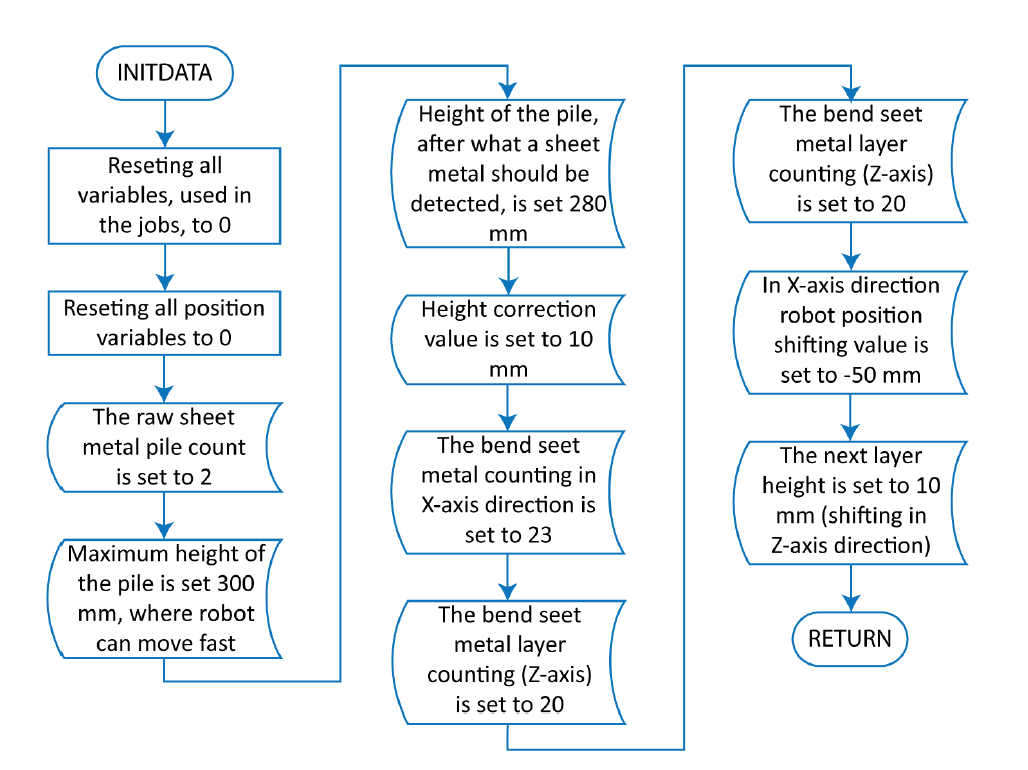
Figure 4. Job INITDATA flowchart
In the first part of the job (lines 4-17 in Table 2) all variable, used in jobs presented here, values are set to 0. Then initial values for material piles are set in the following variables (lines 22-29 in Table 2):
- B005 – defines the number of material piles, from where the robot takes sheet metal for bending. In this program sample the max number of piles is 2. However, it is possible to set the value to 1 if less bend products have to be made.
- B010 – a variable, which also holds the material pile number. It is used to restore the material pile number in variable B005, when new piles have been added to the robot bending cell and it continues its work. This allows to bend more than 2 piles of materials.
- D001 – sets the maximum height of the material pile. In this case, it is set to 300 mm and the piles are not made higher. To this height the robot can move fast.
The 300 mm has to be written in the program as 300000 since the decimal places of position value have to be considered. A position value has three decimal places. Rotation has two decimal places. - D002 – sets the height after what the sheet metal (raw material) can been found and gripped by the robot in the pile. This means, that the piles should be not higher than 280 mm.
- D003 – used to move a position 10 mm higher, so that the robot can move faster near to the materials and then move slower to grab the material.
Following variables hold the numbers of bend products that can be placed in a box/euro pallet (lines 35-37 in Table 2):
- B040 – stores the number of products (23) which can be placed in X-axis direction as one layer on the pallet.
- B041 – stores the number layers of products (20) which can be placed on top of each other (in Z-axis direction).
So, the euro pallet is able to hold bend products. Generally, this numbers are found when the robot program is made and tested first time. Only advice is that the euro pallet (box) should not be too full. Otherwise, the products may fall of the euro pallet when moving the pallet.
Last variables hold position values for shifting robot arm motions by the box, when placing bend sheet metals in it (lines 42-43 in Table 2).
- P040 – used to shift robot positions as needed.
- P041 – holds value (-50 mm) which allows to shift robot motion in X-axis direction.
- P042 – holds value (10 mm) which allows to shift robot motion in Z-axis direction (on which height the next layer is).
Each axis value is hold in a separate variable, so that only one axis is affected at time when the shifting value is calculated (found) (ch 3.9).
2.3 Job: ROBHOME
The job named ROBHOME (Figure 5 and Table 3) is used to move the robot (arm and the external axis) to a neutral (home) position and then the end-effector vacuum is switched off (the tool is set to initial state). The neutral position should be selected so, that it does not prevent the robot operator from servicing the bending machine, changing the euro pallet (box) with bend sheet metals, add new piles of raw sheet metals on the feeding table, etc.
Table 3. Job ROBHOME with comments
| Line nr | Instruction line | Comment |
| 0 | NOP | Beginning of the job |
| 1 | '-------------------- | Separation line to structure the robot job |
| 2 | 'ROBOT home position (0 pos) | Comment about the code in the job |
| 3 | '-------------------------- | |
| 4 | MOVJ VJ=80.00 | Robot moves to home position with 80% of max speed. The robot home position has been saved in this command |
| 5 | CALL JOB:VACUUM_OFF | Calls job named VACUUM_OFF, to switch the end-effector vacuum off |
| 6 | RET | Returns back to the job from where it was called |
| 7 | END | Marks the job end |
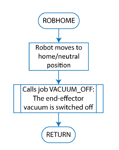
Figure 5. Job ROBHOME flowchart
This job can be called out in different places in the robot program, when the robot needs to move to a neutral position.
2.4 Jobs for controlling the end-effector
In this sample, the end-effector uses suction cups to grip sheet metal. However, mechanical gripper, foam gripper, magnets, etc., can also be used to grip materials from a pile. It all depends on the properties and shape of the material to be gripped by the robot.
The first job (Table 4 and left side of Figure 6) activates vacuum to grip the sheet metal (material) and the second job (Table 5 and right side of Figure 6) deactivates the vacuum.
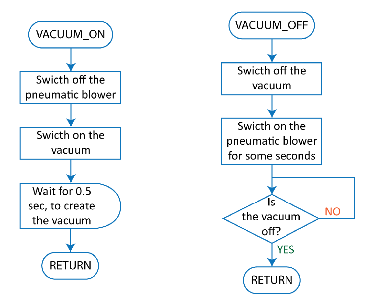
Figure 6. End-effector control: VACUUM_ON and VACUUM_OFF
Table 4. Job VACUUM_ON with comments
| Line nr | Instruction line | Comment |
| 0 | NOP | Beginning of the job |
| 1 | DOUT OT#(2) OFF | Switches off the pneumatic blower |
| 2 | DOUT OT#(1) ON | Switches on the vacuum |
| 3 | TIMER T=0.50 | Waits for 0.5 sec |
| 6 | RET | Returns back to the job from where it was called |
| 7 | END | Marks the job end |
In job VACUUM_ON (line 1) the pneumatic blower is switched off, so that it does not prevent the creation of the vacuum. In 2 line the vacuum generator is switched on and after that robot waits for 0.5 seconds. This time is required to create a vacuum between the robot’s end-effector and the metal sheet. Otherwise, the vacuum may not be created when the robot starts to do something else (like moves immediately away from the sheet metal pile). With line 6 the job is ended and the program execution continues in the job from where this job was called.
Table 5. Job VACUUM_OFF with comments
| Line nr | Instruction line | Comment |
| 0 | NOP | Beginning of the job |
| 1 | DOUT OT#(1) OFF | Switches off the vacuum |
| 2 | PULSE OT#(2) | Sends a pulse signal to the blower |
| 3 | WAIT IN#(1)=OFF | Waits for vacuum off signal from the vacuum sensor |
| 6 | RET | Returns back to the job from where it was called |
| 7 | END | Marks the job end |
In job VACUUM_OFF (line 1) the vacuum is switched off and then a positive signal pulse (signal 1 for 0.3 seconds is set) is sent to the pneumatic blower. The pneumatic blower is used to release the sheet metal form the robot’s end-effector (blows the sheet metal away from the end-effectors suction cups). In line 3 the robot waits for the vacuum sensor signal to disappear. The vacuum sensor is used to see if vacuum has been created or not. In line 6 the job is ended and the program execution continues in the job from where the job VACUUM_OFF was called.
2.5 Job: LOAD
The job called LOAD (Figures 7 and 8, and Table 6) is used to take a sheet metal from two raw material piles on the feeding table. It also controls that there are materials in the pile. If not, then it takes next pile (second pile) for feeding or pauses the robot work so that the robot operator can add new raw materials on the feeding table.
Table 6. Job LOAD with comments
| Line nr | Instruction line | Comment |
| 0 | NOP | Beginning of the job |
| 1 | '------------------------------ | Separation line to structure the robot job |
| 2 | 'Loading of raw material | Comment about the code in the job |
| 3 | '------------------------------ | |
| 4 | '------------------------------ | |
| 5 | 'Set ref points for each pile | Comment about the code in the job |
| 6 | '------------------------------ | |
| 7 | JUMP *HAE1 IF B005=1 | Jumps to label *HAE1, if first pile has been emptied (variable B005 is equal to 1) |
| 8 | JUMP *HAE2 IF B005=2 | Jumps to label *HAE1, if no piles have been used up (variable B005 is equal to 2) |
| 9 | *HAE1 | Label, to where the program will jump when 1 pile has been used up |
| 10 | 'Pile-1 | Comment |
| 11 | REFP 1 | Sets the second piles lowest point as reference point for position conversation |
| 12 | JUMP *HAE | Jumps to label *HAE |
| 13 | '------------------------------ | |
| 14 | *HAE2 | Label, to where the program will jump when no pile has been used up |
| 15 | 'Pile-2 | Comment |
| 16 | REFP 1 | Sets the second piles lowest point as reference point for position conversation |
| 17 | '------------------------------ | |
| 18 | *HAE | Label, to where the program will jump |
| 19 | JUMP *OVER IF B002>=1 | Jumps to label *OVER, if in the pile a sheet metal was detected and gripped by the end-effector |
| 20 | '------------------------------ | |
| 21 | 'Finding pos for new pile/stack | Comment |
| 22 | '------------------------------ | |
| 23 | GETS PX100 $PX011 | A piles lowest position variable $P011 pules values are stored to position variable P100 |
| 24 | CNVRT PX100 PX100 RF | Converts position pulse values to XYZ type values and saves in position variable P100. In line 11 or 16 set reference point is used as the conversion reference point |
| 25 | SET P101 P100 | Position variable P100 values are saved to position variable P101 |
| 26 | SET P102 P100 | Position variable P100 values are saved to position variable P102 |
| 27 | SET P103 P100 | Position variable P100 values are saved to position variable P103 |
| 28 | SUB P104 P104 | The SUB instruction is used to reset position variable P0104 values (all coordinates are set to 0) |
| 29 | SETE P104 (3) D001 | Variable D001 value (300 mm) is saved as position variable P104 Z-axis value (the height is set to 300 mm) |
| 30 | ADD P101 P104 | Position variable P101 values are increased with P104 values. The position is lifted up by 300 mm |
| 31 | SETE P104 (3) D002 | Variable D002 value (280 mm) is saved as position variable P104 Z-axis value (the height is set to 280 mm) |
| 32 | ADD P102 P104 | Position variable P102 values are increased with P104 values. The position is lifted up by 280 mm |
| 33 | '------------------------------ | |
| 34 | 'Searching for the material | Comment |
| 35 | '------------------------------ | |
| 36 | *OVER | Label, to where the program will jump, when instruction lines 23-33 are not executed |
| 37 | MOVJ P101 EX100 VJ=45.00 | Robot moves by joint interpolation to position saved in position variable P101 (a lot above a material pile) with 45% of maximum speed |
| 38 | MOVL P102 EX100 V=350.0 | Robot moves by linear interpolation to position saved in position variable P102 (above a material pile) with speed of 350 mm/s |
| 39 | CALL JOB:VACUUM_ON | Calles job named VACUUM_ON, where the vacuum is switched on |
| 40 | TIMER T=0.20 | Waits for 0.2 sec |
| 41 | MOVL P103 EX100 V=11.0 UNTIL IN#(1)=ON | Robot moves by linear interpolation to position saved in position variable P103 (lowest position of the pile) with speed of 11 mm/s. The motion is stopped when vacuum sensor is activated (a sheet metal has been gripped) |
| 42 | TIMER T=0.50 | Waits for 0.5 sec. After the time robot should be standing still |
| 43 | 'Finding a new upper pos | comment |
| 44 | GETS PX102 $PX000 | Robots current position (is given by variable $P000) pulse values are stored to position variable P102 |
| 45 | CNVRT PX102 PX102 RF | Converts position pulse values to XYZ type values and saves in position variable P102. In line 11 or 16 set reference point is used as the conversion reference point |
| 46 | SUB P104 P104 | The SUB instruction is used to reset position variable P0104 values (all coordinates are set to 0) |
| 47 | SETE P104 (3) D003 | Variable D003 value (10 mm) is saved as position variable P104 Z-axis value (the height is set to 10 mm) |
| 48 | ADD P102 P104 | Position variable P102 values are increased with P104 values. The position is lifted up by 10 mm |
| 49 | SET B002 1 | Value 1 is given to variable B002. This marks that a sheet metal was taken by the robot from a pile |
| 50 | JUMP *OK IF IN#(1)=ON | Jumps to label *OK, if the end-effector has gripped a sheet metal in the pile |
| 51 | '------------------------------ | |
| 52 | 'No material! | This marks the code part, what the robot has to execute if the end-effector did not grip a sheet metal in a pile |
| 53 | '------------------------------ | |
| 54 | CALL JOB:VACUUM_OFF | Calles job named VACUUM_OFF, where the vacuum is switched off |
| 55 | MOVL P102 EX100 V=100.0 | Robot moves by linear interpolation to position saved in position variable P102 (above a material pile) with speed of 100 mm/s |
| 56 | MOVJ P101 EX100 VJ=20.00 | Robot moves by joint interpolation to position saved in position variable P101 (a lot above a material pile) with 20% of maximum speed |
| 57 | DEC B005 | Subtracts 1 from variable B005. It shows that one pile of materials has been used up or no material was found there |
| 58 | SET B002 0 | Value 0 is given to variable B002. This marks that noting was taken by the robot from a pile |
| 59 | CALL JOB:ROBHOME | Calles job named ROBHOME, where the robot is moved to home position |
| 60 | PAUSE IF B005=0 | Pauses the robot work if variable B005 value is 0 (all piles have been used up) |
| 61 | '------------------------------ | |
| 62 | 'ADD new material !!! | This are instructions for the robot operator. New materials should be added and then the program execution should be continued |
| 63 | 'ADD new material !!! | |
| 64 | 'Reset safety and press play | |
| 65 | '------------------------------ | |
| 66 | RET | Returns back to the job from where it was called |
| 67 | '------------------------------ | |
| 68 | 'Material gripped | This marks the code part, what the robot is executing when the end-effector did grip a sheet metal in a pile |
| 69 | '------------------------------ | |
| 70 | *OK | Label, to where the program will jump, when instruction lines 55-67 are not executed |
| 71 | TIMER T=0.50 | Waits for 0.5 sec. Is needed for better griping the sheet metal |
| 72 | MOVL P102 EX100 V=15.0 | Robot moves by linear interpolation to position saved in position variable P102 (above a material pile) with speed of 15 mm/s |
| 73 | MOVL P101 EX100 V=400.0 ACC=20 | Robot moves by linear interpolation to position saved in position variable P101 (a lot above a material pile) with speed of 400 mm/s. Also, the maximum acceleration value is set to 20% |
| 74 | RET | Returns back to the job from where it was called |
| 75 | END | Marks the job end |
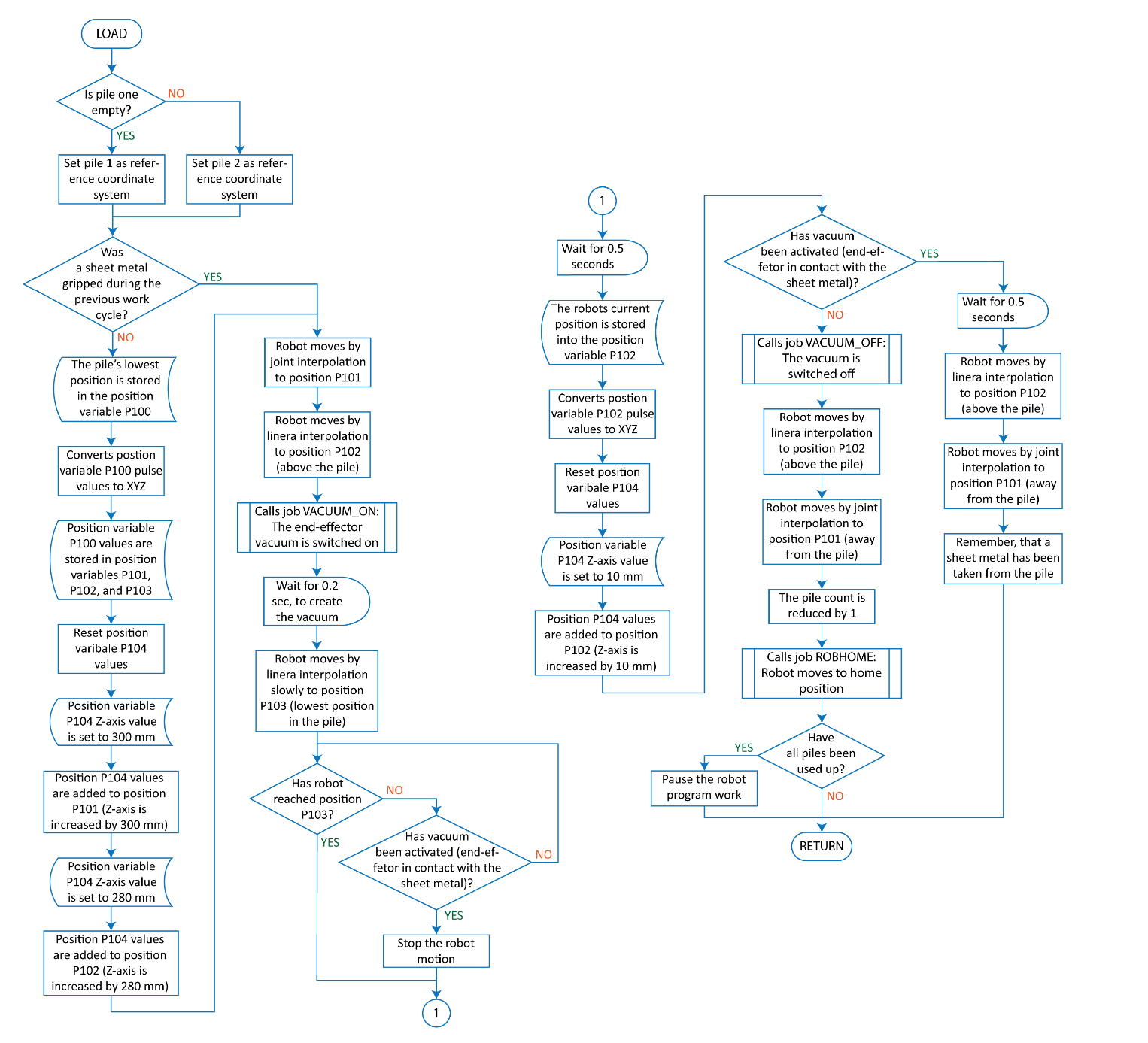
Figure 7. Job LOAD flowchart
In lines 7-8 robot selects a pile for taking raw materials. In line 11 the first pile’s lowest point and in line 16 the second pile’s (first pile is empty) lowest point is taken as reference coordinate system for finding the positions used for picking the sheet metal from the pile (Figure 8).
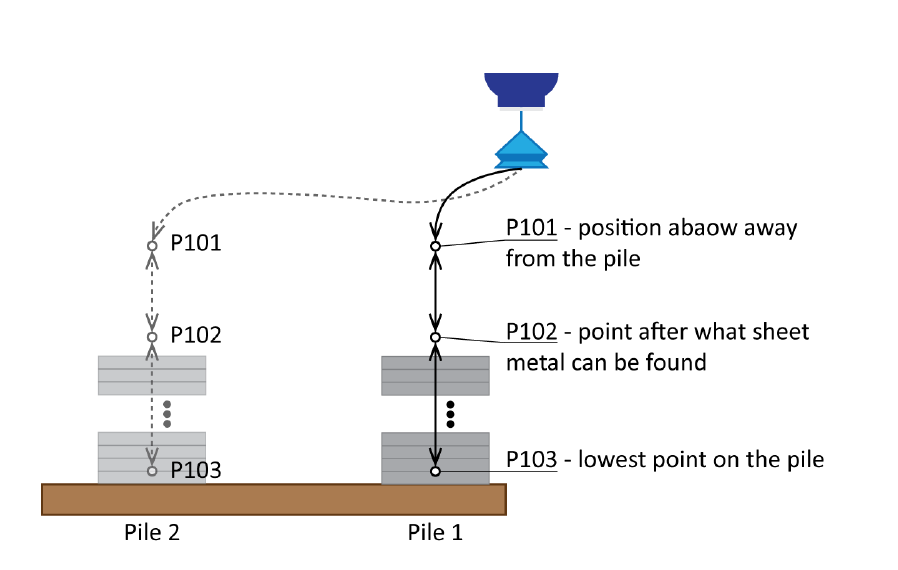
Figure 8. How the robot moves, when taking sheet metal from feeding table
In line 19 robot program jumps over the position calculations when in the previous work cycle the robot grabbed a sheet metal (variable B002 has this information).
In line 23 the position variable P011 values are given to position variable P100. The position P011 is the lowest pick up position in a pile, which has been taught (it can be retaught if needed). In next line (line 24) the position point values are converted into XYZ type values. In line 11 or 16 set reference coordinate system is used in the position value conversation.
In lines 25-27 position variable P100 (lowest position in the current pile) values are stored in position P101, P102, and P103. Then position variable P104 values are set to 0. With lines 29-32 the position variables P101 and P102 are moved up (in Z-axis direction). The first one is moved by 300.000 mm and the second by 280.000 mm (Figure 9). The position P104 is used for this purpose. Only Z-axis values is changing in the positions variable P104. Other axis’s (X and Y) values are on 0.
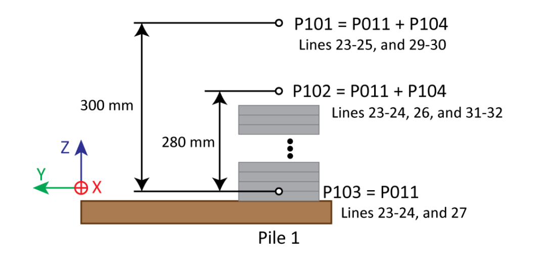
Figure 9. Calculating upper positions for taking sheet metals from the pile
With lines 37-38 robot moves above the pile. The last motion has to be straight, so that the robot does not crash into the material pile or other objects. Then the job VACUUM_ON is called to switch on the vacuum on the end-effector. After 0.2 seconds (line 40) the robot moves down toward position variable P103 until the vacuum sensor detects that the end-effector has gripped a sheet metal (line 41) (Figure 10). However, it is possible that the robot may reach the position saved in the position variable P103.
In line 42 the robot waits for 0.5 seconds so that that the robot motion can be completed. And after the time has elapsed, the robot should remain still. This is need for line 44 to get accurate real position values of the robot. So, in line 44 real robots current position values are taken and saved in P102. Then the position P102 pulse values are converted into XYZ type values. Reference coordinate system set in line 11 or 16 are used here. With lines 46-48 the position variable P102 is moved up by 10 mm (Figure 11). This is done to avoid fast motion near the raw material pile. If the robot moves to fast and touches the sheet metal on top of the sheet metal pile, then other sheet metals in the pile may shift and later gripping problems may arise (not able to pick up sheet metal).
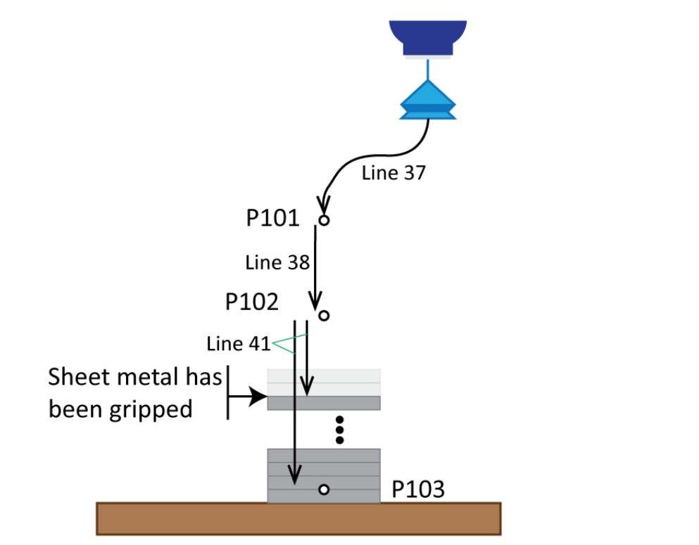
Figure 10. Robot takes a sheet metal from the pile |
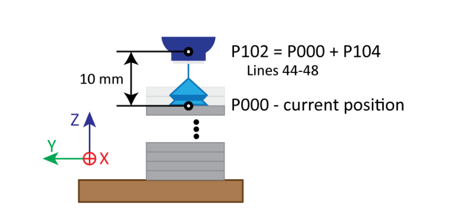
Figure 11. Calculating new position for P102 |
The line 49 is used to remember that in the list cycle a metal sheet was taken from a pile. Variable B002 is used for this purpose.
Line 50 controls that the vacuum is active or not. Active vacuum shows that the sheet metal has been gripped successfully and the program execution continues from line 70. If not, then the program continues and calls job VACUUM_OFF to switch the vacuum off (line 54).
With lines 55-56 the robot moves up away from the pile (Figure 12). First straight up and then with joint interpolation more away. The pile count (variable B005) is decreased by one and variable B002 value is set to 0. This shows that the sheet metal was not gripped and the materials from next pile should be taken for bending.
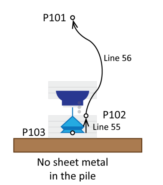
Figure 12. Robot moves away without sheet metal |
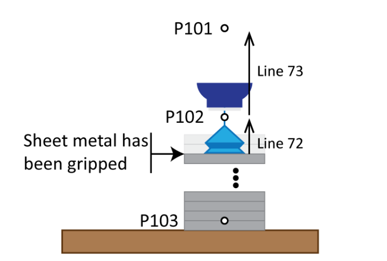
Figure 13. Robot moves way with sheet metal |
In line 59 job ROBHOME is called to move the robot to home position. In the next line the robot program execution is paused when there are no piles of materials on the feeding table. This is shown by variable B005.
Lines 62-64 are used to give commands to the robot operator (this are comments in the job). The robot operator should fill up the feeding table with new raw materials and then press play to continue the robot program execution. In this case, this job execution is ended (line 66) and robot program jumps back the job called MAIN.
However, if the material was gripped, then the robot waits for 0.5 seconds (line 71) and then move straight up from the pile (Figure 13). In the beginning slowly to position P102 (line 72) and then faster by increasing the speed to position P101 (line 73).
With line 74 the job is ended and the program execution continues in the job (MAIN) from where this job was called.
2.6 Job: ZEROTABLE
The job called ZEROTABLE (Figure 14 and Table 7) is used to position the sheet metals so that they go into the bending machine always the same way (orientation and position). The sheet metals are gripped from the same spot/position and therefore the bends are made in correct places. Normally the sheet metals are misaligned (shifted and rotated by a small margin like 0.1-2 mm/degree) in a pile. This means that the end-effector is not gripping the sheet metals from the same spot as it was done when the program was created. This small misalignment is enough that the bends are made in wrong places and faulty products are made. The misalignment may even happen when the robot is gripping sheet metal from the pile (sheet metals are moving around).
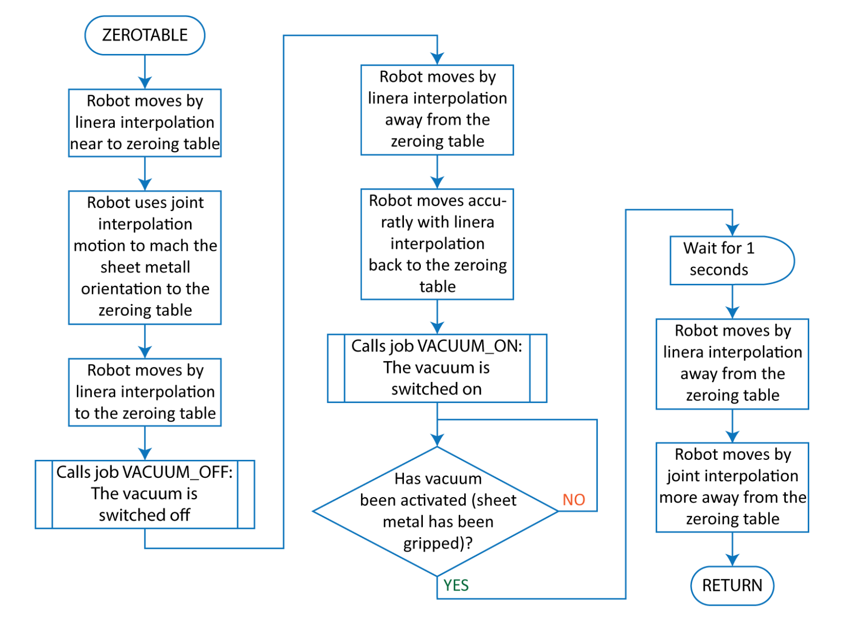
Figure 14. Job ZEROTABLE flowchart
In this job motion instructions use local position variables, which are not shown on the teach pendant screen (Figure 15). The position variable name starts with letter C.

Figure 15. Job ZEROTABLE opened in teach pendant screen
Table 7. Job ZEROTABLE with comments
| Line nr | Instruction line | Comment |
| 0 | NOP | Beginning of the job |
| 1 | '------------------------------ | Separation line to structure the robot job |
| 2 | 'Place material to pos table | Comment about the code in the job |
| 3 | '------------------------------ | |
| 4 | MOVL V=500.0 | Robot moves by linear interpolation near to the zeroing table with speed of 500 mm/s |
| 5 | MOVJ VJ=35.00 | Robot moves by joint interpolation to match the sheet metal orientation to the zeroing table with 35% of max speed |
| 6 | MOVL V=200.0 | Robot moves by linear interpolation to the zeroing table with speed of 200 mm/s |
| 7 | CALL JOB:VACUUM_OFF | Calls job named VACUUM_OFF, to switch the end-effector vacuum off to release the sheet metal |
| 8 | MOVL V=700.0 | Robot moves by linear interpolation away from the zeroing table with speed of 700 mm/s |
| 9 | MOVL V=50.0 PL=0 | Robot moves by linear interpolation back to the zeroing table with speed of 50 mm/s. The motion positioning level has been set to maximum (exact positioning) |
| 10 | CALL JOB:VACUUM_ON | Calls job named VACUUM_ON, to switch the end-effector vacuum on to grip the sheet metal |
| 11 | WAIT IN#(1)=ON | Waits until vacuum on signal comes from the vacuum sensor |
| 12 | TIMER T=1.00 | Waits for 1 sec. With this the end-effector should be able to grip the sheet metal very well |
| 13 | MOVL V=150.0 | Robot moves by linear interpolation away from the zeroing table with speed of 150 mm/s |
| 14 | MOVJ VJ=35.00 | Robot moves by joint interpolation more away from the zeroing table with 35% of the max speed |
| 15 | RET | Returns back to the job from where it was called |
| 16 | END | Marks the job end |
In line 4 the robot moves straight near to the zeroing table (Figure 16). Then reorients the sheet metal so that it is parallel to the zeroing table (line 5). With line 6 the robot places the sheet metal on the zeroing table (positioning table). The position on the table is chosen so that there is 2 cm (not more) free space from the bottom and from the left edges of the sheet metal to the bottom and left edges of the table (Figure 17). The position in the motion instruction of line 6 can be retaught, if needed. After line 6 the robot positions in the job should not be changed. Otherwise the bending points/lines will shift and the robot bending cell will produce faulty products.
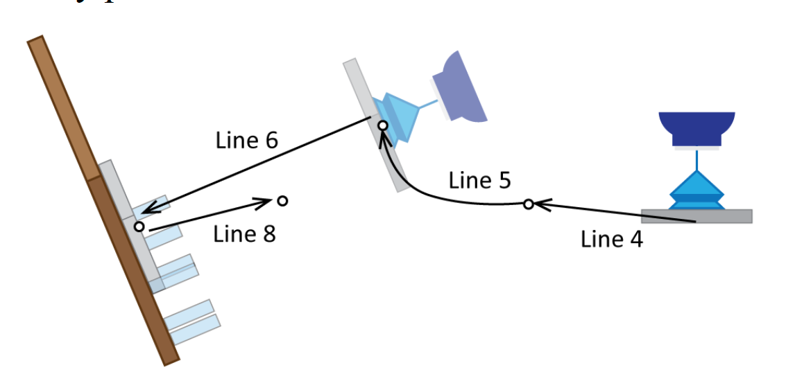
Figure 16. Moving the sheet metal to the zeroing table |
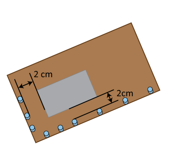
Figure 17. Placing the sheet metal on the zeroing table |
In line 7 the job VACUUM_OFF is called to release the sheet metal and to trop it on the zeroing table. Then the robot moves away and back to the zeroing table with straight motions (lines 8 and 9) (Figure 17 and 18). In line 10 the job VACUUM_ON is called to grip the sheet metal from the zeroing table. Then the robot waits for vacuum on signal (given by the vacuum sensor) and for the time to pass 1 second. The time delay is used to grip better the sheet metal (vacuum has time to build up).
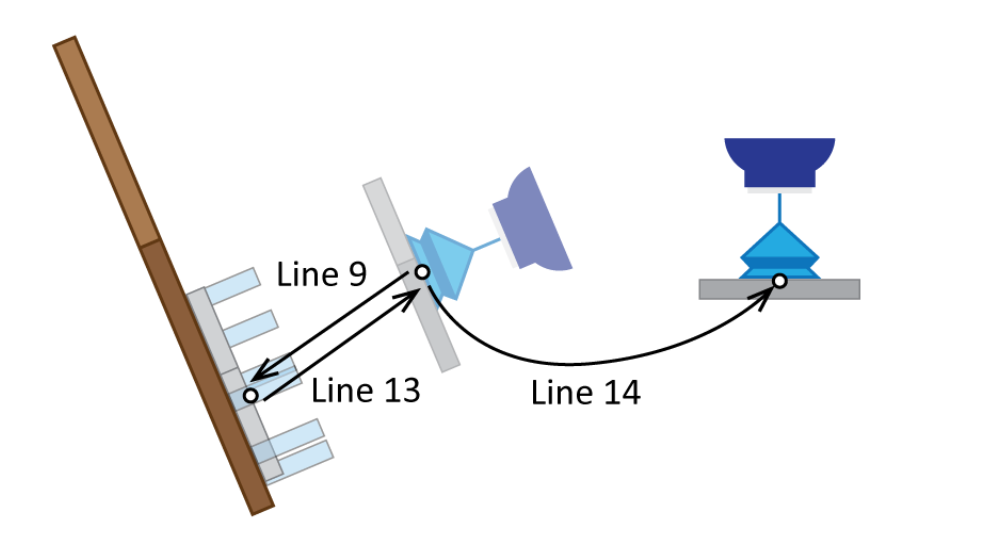
Figure 18. Taking repositioned sheet metal away from the zeroing table
With lines 13 and 14 robot moves away from the zeroing table. The job ends with line 15 and the program execution continues in the job (MAIN) from where this job was called.
2.7 Job: BEND
Under this chapter a robot program (job) for bending is presented (Figure 19 and Table 8). It should be mentioned that the robot itself is not bending the sheet metal. This is done by the bending machine. The robot only places the sheet metal into the bending machine as needed.
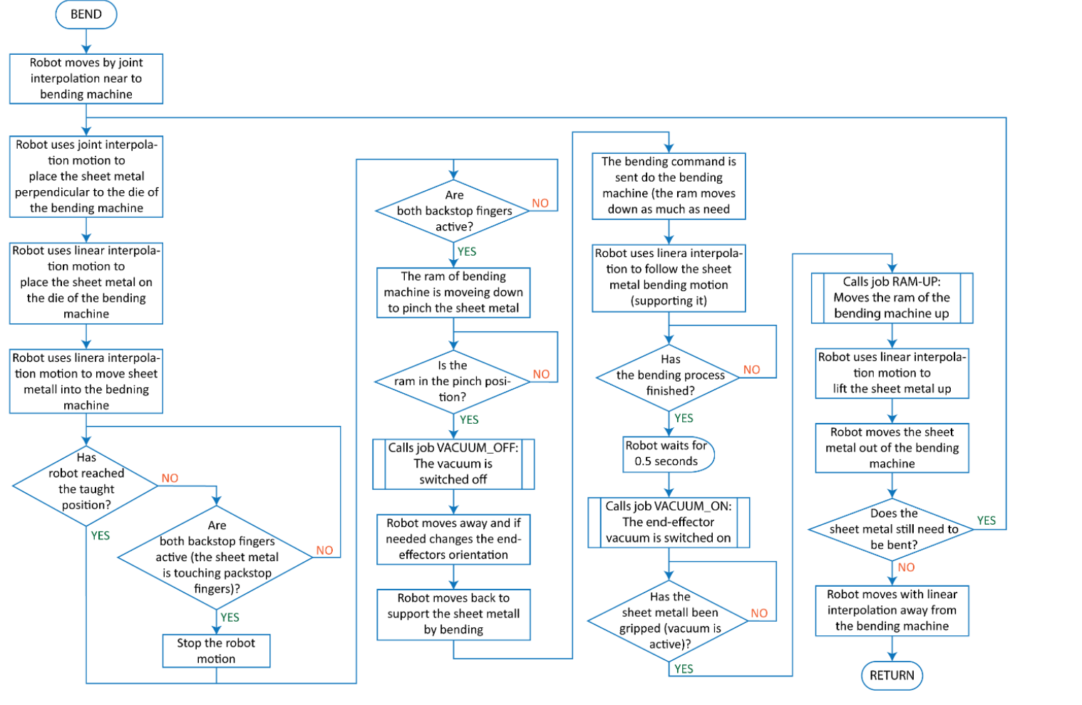
Figure 19, Job BEND flowchart
Table 8. Job BEND with comments
| Line nr | Instruction line | Comment |
| 0 | NOP | Beginning of the job |
| 1 | '------------------------------ | Separation line to structure the robot job |
| 2 | 'Bending the material | Comment about the code in the job |
| 3 | '------------------------------ | |
| 4 | MOVJ VJ=20.00 | Robot moves near to the bending machine and reorients the sheet metal as needed |
| 5 | MOVJ VJ=10.00 | |
| 6 | 'BEND1--------------------------- | First bending starts |
| 7 | MOVL V=50.0 PL=0 | Robot places accurately the sheet metal on the bending machine die (the motion positioning level has been set to maximum) |
| 8 | MOVL V=3.0 PL=0 UNTIL IN#(100)=ON | Robot pushes slowly the sheet metal into the bending machine until both backstop fingers (back gauges) are active. Some times the motion ends without getting the signals form the backstop fingers |
| 9 | WAIT IN#(100)=ON | Waiting for a signal from both backstop fingers (they are touching the sheet metal) |
| 10 | DOUT OT#(13) ON | The ram of the bending machine has to move down to pinch the sheet metal. The command is sent over general purpose output 13, which is switched on |
| 11 | WAIT IN#(12)=ON | Robot waist until the bending machine ram is in the pinch position. This information is sent over general purpose input 12 |
| 12 | CALL JOB:VACUUM_OFF | Calls job named VACUUM_OFF, to switch off the end-effector vacuum (releasing the sheet metal) |
| 13 | MOVL V=400.0 | Robot moves by linear interpolation away from the sheet metal |
| 14 | MOVL V=700.0 | Robot changes the position (orientation) of the end-effector |
| 15 | MOVL V=650.0 | Robot changes the position (orientation) of the end-effector |
| 16 | MOVL V=500.0 | Robot moves (linear interpolation) near to the sheet metal to support it |
| 17 | DOUT OT#(14) ON | The bending command is sent to the bending machine. General purpose output 14 is switched on |
| 18 | MOVL V=500.0 | Robot (end-effector) follows the sheet metal to support it during the bending |
| 19 | MOVL V=100.0 | Robot moves near to the sheet metal (still following) |
| 20 | WAIT IN#(13)=ON | Robot waits until the bending process has been finished (the ram has reached the lowest point). This information is sent over general purpose input 13 |
| 21 | TIMER T=0.50 | Robot waits for 0.5 seconds |
| 22 | CALL JOB:VACUUM_ON | Calls job named VACUUM_ON, to switch the end-effector vacuum on to grip the sheet metal |
| 23 | WAIT IN#(1)=ON | Waits until vacuum on signal comes from the vacuum sensor |
| 24 | CALL JOB:RAM-UP | Calls job named RAM-UP, to move the ram of the bending machine up |
| 25 | MOVL V=150.0 | The sheet metal is moved up and away from the bending machine die |
| 26 | MOVL V=500.0 | |
| 27 | MOVL V=500.0 | |
| 28 | MOVL V=600.0 | |
| 29 | 'BEND2--------------------------- | Second bending |
| 30 | MOVL V=350.0 | The sheet metal orientation is changed as needed |
| 31 | MOVL V=150.0 | |
| 32 | MOVL V=150.0 PL=0 | Robot places accurately the sheet metal on the bending machine die |
| 33 | MOVL V=3.0 UNTIL IN#(100)=O | Robot pushes slowly the sheet metal into the bending machine until both backstop fingers (back gauges) are active |
| 34 | WAIT IN#(100)=ON | Robot waits until both backstop fingers are touching the sheet metal |
| 35 | DOUT OT#(13) ON | The ram of the bending machine has to move down to pinch the sheet metal |
| 36 | WAIT IN#(12)=ON | Robot waist until the bending machine ram is in the pinch position |
| 37 | CALL JOB:VACUUM_OFF | Calls job named VACUUM_OFF, to switch off the end-effector vacuum |
| 38 | MOVL V=500.0 | Robot moves away form the sheet metal and changes the end-effector orientation as needed |
| 39 | MOVL V=500.0 | |
| 40 | DOUT OT#(14) ON | The bending command is sent to the bending machine |
| 41 | TIMER T=0.50 | Robot waits for 0.5 seconds |
| 42 | MOVL V=500.0 | Robot follows the sheet metal by bending and supports it |
| 43 | MOVL V=400.0 | |
| 44 | MOVL V=100.0 | |
| 45 | WAIT IN#(13)=ON | Robot waits until the bending process has been finished (the ram has reached the lowest point) |
| 46 | TIMER T=0.50 | Robot waits for 0.5 seconds |
| 47 | CALL JOB:VACUUM_ON | Calls job named VACUUM_ON, to switch the end-effector vacuum on to grip the sheet metal |
| 48 | WAIT IN#(1)=ON | Waits until vacuum on signal comes from the vacuum sensor |
| 49 | CALL JOB:RAM-UP | Calls job named BEND-UP, to move the ram of the bending machine up |
| 50 | MOVL V=150.0 | The sheet metal is away from the bending machine die |
| 51 | 'BEND3-------------------------- | Third bending |
| 52 | MOVL V=150.0 | The sheet metal orientation is changed as needed |
| 53 | MOVL V=100.0 | |
| 54 | MOVL V=30.0 PL=0 | Robot places accurately the sheet metal on the bending machine die |
| 55 | MOVL V=3.0 UNTIL IN#(100)=O | Robot pushes slowly the sheet metal into the bending machine until both backstop fingers (back gauges) are active |
| 56 | WAIT IN#(100)=ON | Robot waits until both backstop fingers are touching the sheet metal |
| 57 | DOUT OT#(13) ON | The ram of the bending machine has to move down to pinch the sheet metal |
| 58 | WAIT IN#(12)=ON | Robot waist until the bending machine ram is in the pinch position |
| 59 | CALL JOB:VACUUM_OFF | Calls job named VACUUM_OFF, to switch off the end-effector vacuum |
| 60 | MOVL V=350.0 | Robot moves away from the sheet metal and changes the end-effector orientation as needed |
| 61 | DOUT OT#(14) ON | The bending command is sent to the bending machine |
| 62 | MOVL V=250.0 | Robot follows the sheet metal by bending and supports it |
| 63 | MOVL V=50.0 PL=0 | Robot moves precisely the end-effector against the sheet metal |
| 64 | WAIT IN#(13)=ON | Robot waits until the bending process has been finished (the ram has reached the lowest point) |
| 65 | TIMER T=0.50 | Robot waits for 0.5 seconds |
| 66 | CALL JOB:VACUUM_ON | Calls job named VACUUM_ON, to switch the end-effector vacuum on to grip the sheet metal |
| 67 | WAIT IN#(1)=ON | Waits until vacuum on signal comes from the vacuum sensor |
| 68 | CALL JOB:RAM-UP | Calls job named BEND-UP, to move the ram of the bending machine up |
| 69 | MOVL V=100.0 | The sheet metal is moved up and away from the bending machine die |
| 70 | MOVL V=500.0 | |
| 71 | 'END-------------------------- | |
| 72 | MOVJ VJ=90.00 | Robot moves away from the bending machine with joint interpolation |
| 73 | MOVJ VJ=100.00 | |
| 74 | RET | Returns back to the job from where it was called |
| 75 | END | Marks the job end |
With lines 4-5 robot moves near to the bending machine and reorients the sheet metal as needed (perpendicular to the die of the bending machine). In line 7 robot places the sheet metal on the die of the bending machine and bushes the sheet metal into the bending machine until both backstop fingers (back gauge) touch it (lines 8-9). Then the ram pinching command is sent to the bending machine and robot waits for confirmation of the execution of the command (lines 10-11). General purpose output 13 and input 12 are used for this.
In line 12 the job VACUUM_OFF is called to release the sheet metal. Then the robot moves away and changes the orientation of the end-effector (lines 13-15). In line 16 robot moves back to support the sheet metal from below with the end-effector. Then the bending command is sent to the bending machine over general purpose output 14 (line 17) and robot starts to follow the sheet metal by the bending process to support it (lines 18-19). Normally, the supporting is done by the end-effector.
In lines 20 and 21 robot waits. In the first part the robot waits for the bending process to end and in second part it waits for the delay time (0.5 seconds) to elapse. The bending process end is marked by the ram’s lowest point and this information is send to the robot over general purpose input 13.
In line 22 the job VACUUM_ON is called to grip the sheet metal and the robot waits for the vacuum on signal (given by the vacuum sensor) (line 23). Then the ram is moved up to release the sheet metal (line 24). This is controlled by the job called RAM-UP. With lines 25-28 the sheet medal is lifted up and moved out from the bending machine. And with this the first bending is finished.
Then the second (lines 30-50) and third (lines 52-70) bend are made. In general, the programs for both bends are same as for the first bend. The difference comes out by the number of used motion instruction to position and place the sheet metal onto the die of the bending machine, to follow the sheet metal to support it by bending, and to take the sheet metal out of the bending machine.
After all the bending’s have been done, the robot moves away from the bending machine with the bend sheet metal (line 72-73) and the job ends (line 74). The program execution continues in the job (MAIN) from where this job was called.
For each product bending the job is unique. Normally it is longer, has more bending’s, and uses different motions to place the sheet metal into the bending machine. Sometimes, it may be necessary to change the sheet metal gripping point, as the end-effector may hinder the placement of sheet metal into the bending machine. For that additional holders (like magnets, grippers, etc.) are installed on the bending machine or zeroing table.
2.8 Job: RAM-UP
The job called RAM-UP (Figure 20 and Table 9) is used to move the ram of the bending machine up. There is an order how this has to be done.
Table 9. Job RAM-UP with comments
| Line nr | Instruction line | Comment |
| 0 | NOP | Beginning of the job |
| 1 | '------------------------------ | Separation line to structure the robot job |
| 2 | 'Move press up | Comment about the code in the job |
| 3 | '------------------------------ | |
| 4 | DOUT OT#(14) OFF | The ram down pressing (bending command) is switched off. For that the general purpose output 14 is switched off |
| 5 | TIMER T=0.60 | Robot waits for 0.6 seconds |
| 6 | DOUT OT#(13) OFF | Th sheet metal pinching command is taken away. For that the general purpose output 13 is switched off |
| 7 | TIMER T=0.60 | Robot waits for 0.6 seconds |
| 8 | DOUT OT#(15) ON | The ram of the bending machine has to move up so that the sheet metal can be lifted out from the bending machine. The command is sent over general purpose output 15, which is switched on |
| 9 | WAIT IN#(14)=ON | Robot waits until the ram has reached the upper dead position of the bending machine. This information is sent over general purpose input 14 |
| 10 | DOUT OT#(15) OFF | The general purpose output 15 is switched off |
| 11 | RET | Returns back to the job from where it was called |
| 12 | END | Marks the job end |
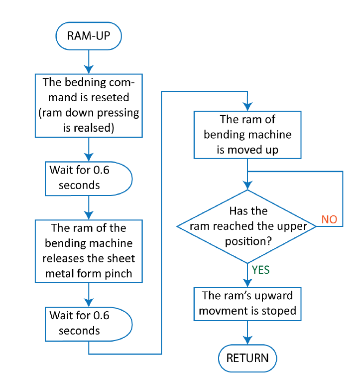
Figure 20, Job RAM-UP flowchart
In the job the bending (line 4) and pinching (line 6) commends are terminated. The corresponding general purpose outputs 14 and 13 are switched off. After each command termination a time delay (0.6 sec) is used to give the bending machine time to react to it. Then the ram of the bending machine is moved up (line 8) until the upper dead position (programmed in the bending machine) has been reached (line 9). The ram up motion is terminated in the line 10.
The job ends with line 11 and the program execution continues in the job (BEND) from where this job was called.
It may be necessary to include robot motion to move the sheet metal up with the ram, if the shape of the bent sheet metal is complex and it can get stuck behind the upper tool (attached to the punch). This is needed to avoid breaking the robot, end-effector, bending machine tools, product, etc.
2.9 Job: STOW-PAL
The job called STOW-PAL (Figure 21 and Table 10) is used to store bend sheet metals away. In this sample the bend sheet metals are placed into a box (Figure 22).
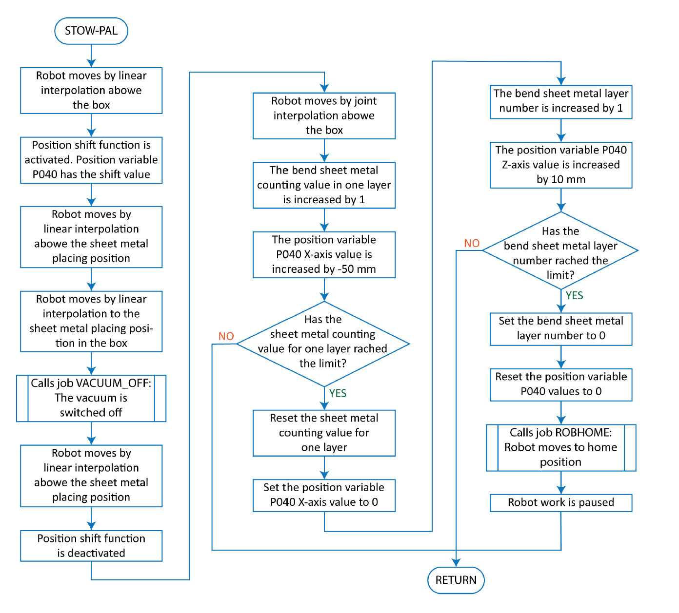
Figure 21. Job STOW-PAL flowchart
Table 10. Job STOW-PAL with comments
| Line nr | Instruction line | Comment |
| 0 | NOP | Beginning of the job |
| 1 | '------------------------------ | Separation line to structure the robot job |
| 2 | 'Stowing products to pallet | Comment about the code in the job |
| 3 | '------------------------------ | |
| 4 | MOVL V=800.0 | Robot moves by linear interpolation above the box with speed of 800 mm/s |
| 5 | '------------------------------ | |
| 6 | 'Lay with shift | Comment |
| 7 | '------------------------------ | |
| 8 | SFTON P040 | The robot position shift function is activated. The shift values are in position variable P040 |
| 9 | '------------------------------ | |
| 10 | 'Set start point | Comment |
| 11 | '------------------------------ | |
| 12 | MOVL V=500.0 PL=0 | Robot moves by linear interpolation above the product placing position in the box with speed of 500 mm/s |
| 13 | MOVL V=150.0 PL=0 | Robot moves by linear interpolation to the product placing position in the box with speed of 150 mm/s |
| 14 | CALL JOB:VACUUM_OFF | Calls job named VACUUM_OFF, to switch off the end-effector vacuum |
| 15 | MOVL V=600.0 | Robot moves by linear interpolation above the product placing position in the box with speed of 600 mm/s |
| 16 | SFTOF | The shift function is deactivated |
| 17 | MOVJ VJ=50.00 | Robot moves by joint interpolation above the box with 50% of max speed |
| 18 | '********* | |
| 19 | ' Products on X axis! | Comment |
| 20 | '********* | |
| 21 | INC B030 | The variable B030 value is increased by 1 (how many products in X-axis direction) |
| 22 | ADD P040 P041 | The position variable P040 X-axis value is increased by ‑50 mm. The value is saved in position variable P041 |
| 23 | '------------------------------ | |
| 24 | 'Set how many pcs on X axis | Comment |
| 25 | '------------------------------ | |
| 26 | RET IF B030<B040 | Returns back to the job from where it was called, when the variable B030 value is less then variable B040 (less than 23 products have been placed in the box in X-axis direction) |
| 27 | SET B030 0 | Value 0 is given to variable B030 (counting products in X-axis direction) |
| 28 | SETE P040 (1) 0 | The position variable P040 X-axis value is set to 0 |
| 29 | '********* | |
| 30 | ' Products on Z axis! | Comment |
| 31 | '********* | |
| 32 | INC B031 | The variable B031 value is increased by 1 (how many products in Z-axis direction, on top of each other) |
| 33 | ADD P040 P042 | The position variable P040 Z-axis value is increased by 10 mm. The value is saved in position variable P042 |
| 34 | '------------------------------ | |
| 35 | 'Set how many pcs on Z axis | Comment |
| 36 | '------------------------------ | |
| 37 | RET IF B031<B041 | Returns back to the job from where it was called, when the variable B031 value is less then variable B041 (less than 20 products have been placed on top of each other in the box in Z-axis direction) |
| 38 | SET B031 0 | Value 0 is given to variable B031 (counting products in Z-axis direction) |
| 39 | SUB P040 P040 | The SUB instruction is used to reset position variable P040 values (all coordinates are set to 0) |
| 40 | CALL JOB:ROBHOME | Calles job named ROBHOME, where the robot is moved to home position |
| 41 | PAUSE | Pauses the robot work |
| 42 | '------------------------------ | |
| 43 | 'Pallet is full! | This are instructions for the robot operator. Full boxes should be replaced and then the program execution should be continued |
| 44 | 'Change the pallet | |
| 45 | 'Reset safety and press play | |
| 46 | '------------------------------ | |
| 47 | RET | Returns back to the job from where it was called |
| 48 | END | Marks the job end |
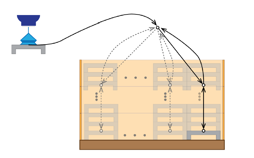
Figure 22. Placing bend sheet metals into a box
With line 4 robot moves near above the box. Then (line 8) the position shift function is activated. The position variable P040 holds the value how much the positions are shifted away from the original place. On the first run the positions are not shifted, because position variable P040 values are 0. On the next run the positions in lines 12-15 are shifted in X-axis direction by -50 mm (Figure 23).
With lines 12 and 13 robot moves straight down into the box to placing position and then releases the bend sheet metal (calls job named VACUUM_OFF to switch off the vacuum). In line 15 robot moves straight up and then deactivates the sift function (line 16). So only positions in lines 12-15 with motion instructions are shifted. With the last motion instruction (line 17) robot moves above the box (Figure 23).
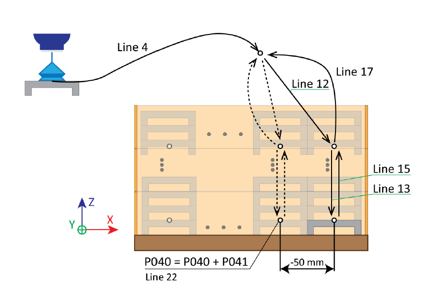
Figure 23. Robot motion positions are shift in X-axis direction
Starting with line 18 the position variable P040 values are changed as needed. In this sample its values change in X- and Z-axis direction. At first, the bend sheet metals are placed in X axis direction as one layer. When the layer is full then the next layer (Z-axis direction) is placed on top of the first one (Figure 24). This is done until maximum number bend sheet metals have been placed into the box.
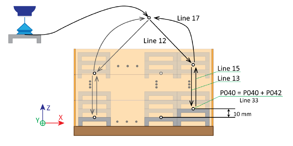
Figure 24. Robot motion positions are shift in Z-axis direction
In X-axis bend sheet metal placing counting variable B030 value is increased by 1 (line 21). Then (line 22) the position variable P041 values are added to the position variable P040. So, the position variable P040 X-axis value increases by -50 mm (after first placing its value is -50, after second -100, after third -150, etc.). Other values are not changed.
With line 26 the job STOW_PAL execution ends (the main job execution continues), when the maximum number of bend sheet metals in one layer has not been reached. The maximum number of bend sheet metals in one layer is given by variable B040 (23 bend sheet metals). If the maximum number has been reached, then the variable B030 value is reset (line 27) and position variable P040 X-axis value is set to 0 (line 28).
Now variable, which are related to Z-axis, values are changed. The layer counting (placing bend sheet metals in Z-axis direction) variable B031 value is increased by 1 (line 32) and position variable P040 Z-axis value is changed by position variable P042 (line 33). The position variable P040 Z-axis value increases by 10 mm (Figure 24). When the first layer is full, then the value is set to 10 mm, after second layer it is 20 mm, after third layer it is 30 mm, etc.
With line 37 the job STOW_PAL execution ends, when the maximum layer number has not been reached. The maximum layer number is given by variable B041 (20 layers). If the maximum layer number has been reached, then variable B031 and position variable (P040) values are set to 0 (lines 38 and 39). With line 40 robot is moved to home position (calls job named ROBHOME), which allows to replace full box with empty box by the robot operator. Line 41 pauses the robot job execution. Lines 43-45 informs the robot operator what has happened and what she/he should do.
The job ends with line 47 and the program execution continues in the job (MAIN) from where this job was called. This is done without any conditions.
2.10 Recommendations to improve the robot program
Each main part of the robot bending cell (feeding table, zeroing table, bending machine, box or euro pallet to stow the bend sheet metals) should have their own user coordinate systems. When the robot bending cell is moved to another place in the factory, then only the user coordinates have to be updated. The position, used in the motion instruction, locations are updated automatically (re calculated), when the new user coordinate is applied.
Sometimes the robot is left above the feeding table when adding new sheet metal piles. This saves time, because the robot does not need to move to home position and then back to the feeding table. The robot can take sheet metals right away.
Landmarks (corners, edges, reeling, etc.) should be used to mark the position of boxes (euro pallet), sheet metal piles, etc. This allows to place them always in the same spot and the need to retrain the positions disappears. It is possible to use sensors (infrared, lidar, etc.) or even cameras to detect automatically the position of the box and sheet metal piles. However, this makes the robot bending cell more complex and expensive.
In chapter 3.4 presented sample job uses 1 general purpose input and 2 general purpose outputs to control the robots end-effector with suction cups. So, the end-effector has only one group of suction cups to grip the sheet metal. Sometimes the suction cups are divided into 2, 3 or even bigger number of groups allowing to use the same end-effector to grip different size sheet metals (sometimes they may have holes). A hole under the suction cup prevents the formation of a vacuum (too much air is taken in and the vacuum cannot be created). The use of groups allows to avoid the use of suction cups under which a hole or emptiness can be found.
It is good to use quick tool changers to exchange the end-effectors by the robot. It expands the list of bend sheet metals, which can be made in the robot bending cell. Following companies offer such devices:
- ATI Industrial Automation
- DESTACO
- SCHUNK
Zhengzhou Linghang Robot Co.