2.1 Industrial robot configuration and basic parameters
An Industrial Robot is defined by ISO 8373 as an automatically controlled, reprogrammable, multipurpose manipulator, programmable in three or more axes.
- https://en.wikipedia.org/wiki/Industrial_robot
- Robotic Industries Association RIA (North America) http://www.roboticsonline.com
- International Federation of Robotics http://www.ifr.org
- Nof, Shimon, Y. (editor) (1999) Handbook of Industrial Robotics. John Wiley & Sons. ISBN 0-471-17783-0
Basic technological capabilities of industrial robots
- Number of axes (degree of freedom) two axes are required to reach any point in a plane, three axes are required to reach any point in space. To fully control the orientation of the end of arm, three more axes are required
- Working envelope the region of space a robot can reach
- Kinematics the actual arrangement of rigid members and joints in the robot, which determines the possible motions
- Carrying capacity or payload shows how much weight a robot can lift
- Speed – how fast the robot can position the end of its arm
- Acceleration – how quickly the axes can accelerate
- Accuracy – how closely a robot can reach a commanded position
- Repeatability – how well the robot will return to a programmed position
Robot anatomy
Robot anatomy stands on the joints and links, which are basic in forming the coordinate systems of industrial robots. Joints provide relative motion. Links are rigid members between joints.
Robot manipulator consists of two sections:
- Body-and-arm – for positioning of objects in the robot’s work volume.
- Wrist assembly – for orientation of objects.
A robotic joint provides relative motion between two links of a robot. Each joint, or axes, provides a certain degree of freedom (dof) of motion. In most cases only one degree of freedom is associated with each joint. So a robot ś complexity can be classified according to the total number of degree of freedom they possess.
Mechanical joints of the robots:
- Linear joint- type L joint – the relative movement between the input link and the output link is a translational sliding motion, with the axes of the two links parallel
- Orthogonal joint- type O joint – the relative movement between the input link and the output link is a translational sliding motion, but the output link is perpendicular to the input link
- Rotational joint- type R joint – this provides rotational relative motion, with the axes of rotation perpendicular to the axes of the input and output links
- Twisting joint- type T joint – this provides rotary motion, but the axis of rotation is parallel to the axis of the two links
- Revolving joint- type V joint – the axis of the input link is parallel to the axis of rotation of the joint, and the axis of the output link is perpendicular to the axes of rotation
2.2 Industrial robots basic coordinate systems
Cartesian coordinate system
Cartesian coordinate robot- x-y-z- robot, consists of three sliding joints. Main application area loading, palletizing, transporting, simple works
 |
 |
Cartesian robots are also called rectilinear or gantry robots and have a rectangular configuration. These types of industrial robots have three prismatic joints to deliver linear motion by sliding on its three perpendicular axes (X, Y and Z). They might also have an attached wrist to allow rotational movement. Cartesian robots are used in majority of industrial applications as they offer flexibility in their configuration which make them suitable for specific application needs.
Cylindrical coordinate system
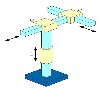
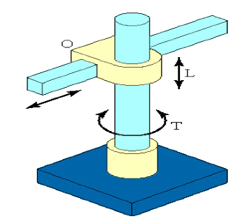
Cylindrical configuration consists of a vertical column, relative to which an arm assembly is moved in and out relative to the axis of the column. Common configuration is to use a T-joint to rotate the column about it axes. An L joint is used to move the arm assembly vertically along the column, while O joint is used to achieve radial movement of the arm. Typically used foe loading- unloading operations of different machine tools.
 |
 |
Robots with a cylindrical coordinate system have a relatively simple structure, where one twisting joint (T) is added to two typical linear coordinates (L). Such type of robots are used for loading-unloading operations, for packing, palletizing, etc. in cases where the robot’s task is to move between different objects in the workplace. Flexibility for the robot can be added with coordinates of the wrist assembly system.
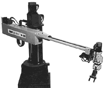
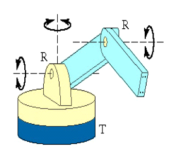
Spherical coordinate system
Jointed-arm robot- general configuration of a human arm. This consists of a vertical column that swivels about the base using T joint. At the top of the column is a shoulder joint (an R joint), output of an elbow joint (another R joint). Robot is very flexible and suits for different applications. Could be used as working robot (welding, painting, assembly, machining, etc) or servicing robot (loading – unloading of different equipment). For transport applications not the best solution.
 |
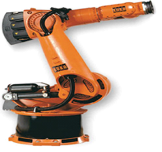 |
Articulated robot (spherical coordinate system) is one of the most common types of industrial robots. It resembles a human arm in its mechanical configuration. The arm is connected to the base with a twisting joint (T). The number of rotary joints (R) connecting the links in the arm can range from two joints to ten joints and each joint provides an additional degree of freedom. The joints can be parallel or orthogonal to each other. Articulated robots having six degrees of freedom are the most commonly used industrial robots as the design offers maximum flexibility.
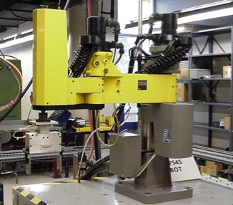
SCARA type robot
SCARA type robot is used for assembly operations. Similar in construction to the jointer-arm-robot, expect that the shoulder and elbow rotational axes are vertical, which means that the arm is very rigid in the vertical direction, but compliant in the horizontal direction. As name, used mainly in assembly works.
 |
 |
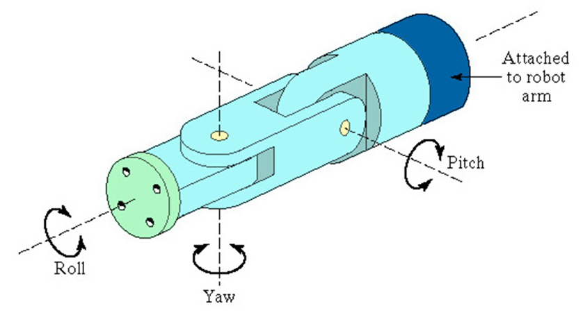
Wrist coordinate system
Wrist assembly is attached to end-of-arm
End effector is attached to wrist assembly
Function of wrist assembly is to orient end effector
Body-and-arm determines global position of end effector
Robot basic construction
There are two basic parts of the robot manipulator:
- a body-and-arm assembly, with three degrees of freedom
- a wrist assembly, with two or three degrees of freedom
Work volume
- The work volume or work envilope is the three-dimensional space in which the robot can manipulate the end of its wrist.
- Work envilope (volume) is determined by the number and types of joints in the manipulator, the ranges of various joints, and the physical size of the links.
- Its actual shape is dependent on the robot`s configuration: a polar robotic configuration tends to produce a spherical work volume; a cylindrical configuration has a cylindrical work envilope and a Cartesian co-ordinate robot produces a rectangular work volume.
2.3 Coordinate systems of the robot-cell
The main function of a robot control software (e.g. RobotWare) is the motion control of a robot. The motion of robot’s manipulator joints, the tool or the gripper can be described in different coordinate systems. These coordinate systems are used for the realization of several control functions, including off-line programming, program adjustment, coordination of the motion of several robots or a robot and additional servodrives, jogging motion, copy of programs from one robot to another, etc.
The main coordinate systems used to describe the motion of a robot are shown in Fig. 1.4. In the motion control the control of the gripper or tool motion is the most important. Because different types of grippers and tools have different dimensions, a special point, not depending on the type of the tool and called tool centre point (TCP) is selected. This point is the origin point of the tool coordinate system. A similar point can be used to describe the gripper or the wrist coordinate system. The mutual connections of a tool, a wrist and other coordinate systems are shown in Fig 4.
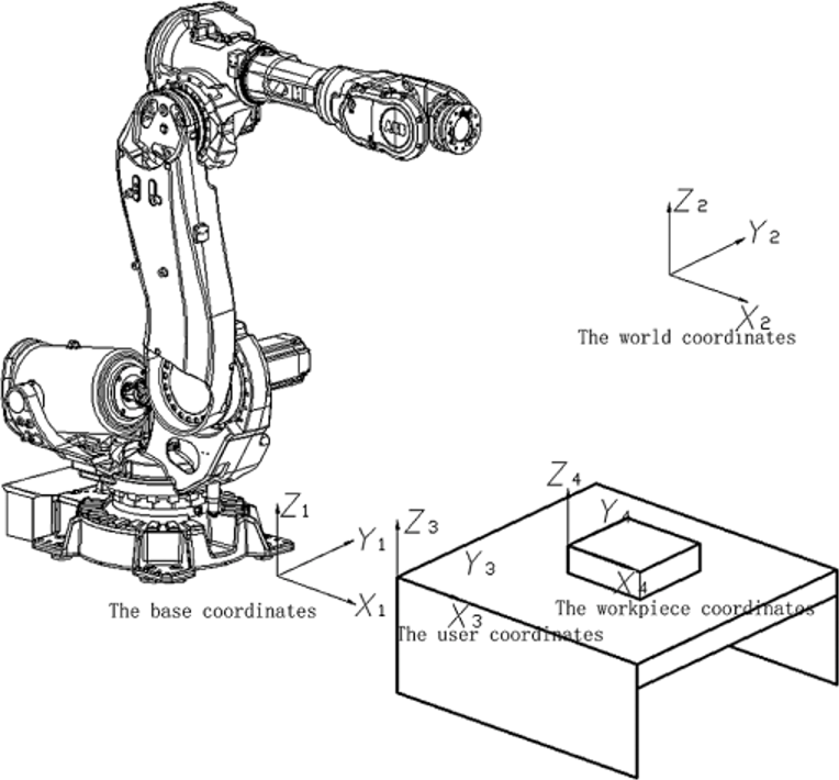
Figure 4 Coordinate systems of an industrial robot
The position of the robot and its movements are always related to the tool centre point (TCP). This point is normally defined as being somewhere on the tool, e.g. on top of the welding electrode or at the centre of a gripper. When a position is recorded, it is the position of the TCP that is recorded. This is also the point that moves along a given path at a given velocity.
If the robot holding a work object and is working on a stationary tool, a stationary TCP is used. If that tool is active, the programmed path and speed are related to the work object.
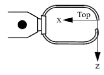
Tool coordinate system The orientation of a tool at a programmed position is given by the orientation of the tool coordinate system. The tool coordinate system refers to the wrist coordinate system, defined at the mounting flange on the wrist of the robot. The tool mounted on the mounting flange of the robot often requires its own coordinate system to enable the definition of its TCP, which is the origin of the tool coordinate system (Fig. 5, a). The tool coordinate system can also be used to get appropriate motion directions when jogging the robot. If a tool is damaged or replaced, the tool coordinate system must be redefined.
Wrist coordinate system In a simple application, the wrist coordinate system can be used to define the orientation of the tool; here the z-axis is coincident with axis 6 of the robot (Fig. 5, b). The wrist coordinate system cannot be changed and is always the same as the mounting flange of the robot in the following respects: The origin is situated at the centre of the mounting flange (on the mounting surface). The x-axis points in the opposite direction, towards the control hole of the mounting flange. The z-axis points outwards, at right angles to the mounting flange.
 |
 |
| a | b |
 |
 |
| c | d |
Figure 5 Tool and wrist coordinates a, b and use of these coordinates with arc and spot welding electrodes c, d
Base coordinate system is linked to the mounting base and stationary base of a robot. In a simple application, programming can be done in the base coordinate system; here the z-axis is coincident with axis 1 of the robot (Fig. 6). In this case:
- The origin is situated at the intersection of axis 1 and the base mounting surface.
- The xy plane is the same as the base mounting surface.
- The x-axis points forwards.
- The y-axis points to the left (from the perspective of the robot). – The z-axis points upwards.
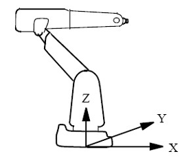
Figure 6 Base coordinate system of a manipulator
For example, floor-mounted robot can be easily programmed in the base coordinate system. If, however, the robot is mounted upside down (suspended), programming in the base coordinate system is more difficult because the directions of the axes are not the same as the principal directions in the working space. In such cases, it is useful to define a world coordinate system.
World coordinate system will be coincident with the base coordinate system if it is not specifically defined. If several robots work within the same working space at a plant, a common world coordinate system is used to enable the robot programs to communicate with one another. It can also be advantageous to use this type of a system when the positions are to be related to a fixed point in the workshop (Fig. 7).
Figure 7 Two robots (one of which is suspended) with a common world coordinate system
The user coordinate system is related to the essential points of the technological process. A robot can work with different fixtures or working surfaces having different positions and orientations. A user coordinate system can be defined for each fixture. If all positions are stored in object coordinates, you will not need to reprogram if a fixture must be moved or turned. By moving (translating or turning) the user coordinate system as much as the fixture has been translated or turned, all programmed positions will follow the fixture and no reprogramming will be required. The user coordinate system is defined based on the world coordinate system (Fig. 8).
Object coordinate system is a coordinate system targeted to an object. Normally the user coordinate system is used to get different coordinate systems for different fixtures or working surfaces. A fixture, however, may include several work objects that are to be processed or handled by the robot. Thus, it often helps to define a coordinate system for each object in order to make it easier to adjust the program if the object is moved or if a new object, the same as the previous one, is to be programmed at a different location. This coordinate system is also very well suited for off-line programming since the positions specified can usually be taken directly from a drawing of the work object. The object coordinate system can also be used when jogging the robot. The object coordinate system is defined based on the user coordinate system (Fig.9).
Figure 8 User coordinate systems that describe the position of two different fixtures
The object coordinate system can be programmed by the numerical definition of characteristic points or by a manual jogging manipulator via characteristic points and automatic storage of these coordinate values in memory.
The programmed positions are always defined relative to an object coordinate system. If a fixture is moved or turned, it can be compensated for by moving or turning the user coordinate system. Neither the programmed positions nor the defined object coordinate systems need to be changed. If the work object is moved or turned, it can be compensated for by moving or turning the object coordinate system.
Figure 9 Object coordinate systems that describe the position of different work objects located in the same fixture
If the user coordinate system is movable, i.e. coordinated external axes are used, then the object coordinate system moves with the user coordinate system. This makes it possible to move the robot in relation to the object even when the workbench is being manipulated.
Sometimes, the same path is to be performed at several places on the same object. To avoid having to re-program all positions each time, a displacement coordinate system can be defined. This coordinate system can also be used in conjunction with searches to compensate for differences in the positions of the individual parts. The displacement coordinate system is defined based on the object coordinate system (Fig. 10).
Figure 10 Translated and rotated displacement coordinate system
Robot’s movements must be initially planned and programmed. Movement planning is based on the selection of coordinate systems and the description of movements in the selected coordinates. After that the movement will be realized with the help of installed robot software.