Sheet metal forming is one of the most common metal manufacturing processes that can be used to produce complex parts with a high degree of dimensional accuracy and increased mechanical properties, along with a good surface finish. Bending is defined as the plastic deformation of sheet metal along a straight line. Bending is a commonly used sheet metal shaping process in various sheet metal industrial products (Tekiner 2004). A bending operation is employed to fabricate parts such as braces, brackets, supports, hinges, angles, frames, channel and other non- symmetrical sheet metal parts which are used in automobiles, aircrafts, ships and various consumer products. There are two types of bending, V-bending and U-bending. The most common one is V- bending and this is subdivided into closed die bending and air bending (Tekiner 2004).
When bending the sheet metal, the material is pressed into the die by means of a stamp to achieve the desired bending angle. The bending angle is determined by the depth of penetration of the stamp die. V-grooved dies are generally used for standard bending operations. Their inaccuracy (poor quality) can make it very time-consuming (with a large amount of scrap) or even impossible to get a good result, which means irreparable scrap and additional costs for the company.
Knowledge of the theoretical basis of bending is very important to take into account both technological possibilities and limitations already in product design. Radius dies, U dies, edge folding dies (hemming), etc. are used for special applications. At first glance, bending may seem like a simple process, but in fact, several factors affect the achievement of an accurate result. The choice of tool dimensions, the type of bending machine used, the type of bending, the type of material and its quality play a great role. All of these have an impact on the quality of the product. The constancy of the properties of the bendable material is also very important (incl. also the stability of the thickness of the material throughout the sheet stack, etc).
Knowledge of the construction of the bending machine and the possible tools and technologies used reduces the time taken to put the products into production and enables the efficient use of the technical equipment available in production. As operators often create programs on the bending machine themselves (especially for small series or smaller workloads) or at least make corrections based on the measurement results of the first part, the acquisition of a good basic knowledge is essential.
The design and implementation of bending technology is a complex activity, where each stage plays an important role in the success of the whole activity. The criteria, needed to take into consideration are:
- cost of the product (semi-finished product);
- duration of the bending cycle (in case of large organizational time costs, consider the application of LEAN methods);
- device setup time (for large setup times, consider implementing SMED);
- quality assurance (in the case of quality problems, the causes must be identified immediately);
- ensuring occupational safety requirements that completely prevent any possibility of accidents at work (consider occupational safety standards).
4.2 Press-brake machine nature and classification
A press brake is a machine pressing tool for bending sheet and plate material, most commonly sheet metal.[1] It forms predetermined bends by clamping the workpiece between a matching punch and die.[2]. Typically, two C-frames form the sides of the press brake, connected to a table at the bottom and on a movable beam at the top. The bottom tool is mounted on the table, with the top tool mounted on the upper beam.[3].
A brake can be described by basic parameters, such as the force or tonnage and the working length.[1] Additional parameters include the stroke length, the distance between the frame uprights or side housings, distance to the back gauge, and work height. The upper beam usually operates at a speed ranging from 1 to 15 mm/s.[3] There are several types of brakes as described by the means of applying force: mechanical, pneumatic, hydraulic, and servo-electric.
In a mechanical press, energy is added to a flywheel with an electric motor. A clutch engages the flywheel to power a crank mechanism that moves the ram vertically. Accuracy and speed are two advantages of the mechanical press.[4]
Hydraulic presses operate by means of two synchronized hydraulic cylinders on the C-frames moving the upper beam.[3][4] Servo-electric brakes use a servo-motor to drive a ball-screw or belt drive to exert tonnage on the ram.
4.2.1 Classification principles
A press-brake machine is a machine tool for bending sheet and plate material, most commonly sheet material. It forms predetermined bends by clamping the workpiece between a matching punch and die.
According to a source of bending force the brake is divided into:
- Mechanical press-brake
- Pneumatic press-brake
- Hydraulic press-brake
- Servo-electric press-brake.
For the mechanical press brake, the vertical movement of the ram is driven by a crank mechanism, which is powered by the flywheel.
The pneumatic press-brake machines makes use of air pressure to move the ram.
Hydraulic press-brake utilizes the two synchronized hydraulic cylinders to move the ram.
Servo-electric brakes use servo motor to drive a ball screw or belt drive to exert force on the ram to make it move vertically.
Today the hydraulic type of press-brake machines becomes most popular all over the world.
From another point of view, the press-brake can be divided into:
- Manual press brake
- Hydraulic press brake
- CNC press brake
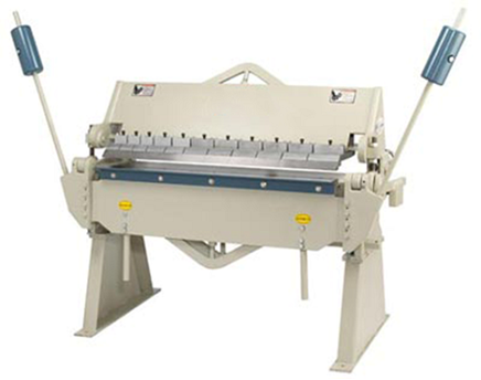
Figure 2. CNC press brake machine
Manual press-brakes are required to adjust the bending dimensions and angles manually when used. It contains work-table, supporters and the clamping plate. The worktable is mounted on the supporters which consists of a base and a pressure plate.
Hydraulic press-brake, classified by synchronization, can be divided into:
- Torsion synchronization press brake
- Hybrid press brake
- Electric-hydraulic synchronization press brake.
By movement they are classified:
- Up-moving press brake
- Down moving press brake
CNC press brake machines are going more and more popular. Their cost is also constantly decreasing compared to conventional equipment. They need less competent staff to deal with them.
CNC press brake consists of:
- Machine frame
- Ram (slider)
- Workbench
- Oil cylinder
- Hydraulic proportional servo system
- Position detection system
- CNC controller
- Electrical control system
CNC press brake realizes bending function by controlling slider stroke and back gauge.
The main advantages of CNC press brake are:
- It is featured with high precision synchronization, high bending accuracy, high repeat positioning accuracy.
- Equipped with a hydraulic automatic clamp or fast clamp for the upper die and socket lower die based on customer`s requirement to reduce the labour intensity and improve production efficiency.
- The back gauge of CNC press-brake can be extended to six axes.
- The separated upper die which is in different lengths can be assembled into a certain width according to the requirements of the workpiece in order to meet the special needs of the fabrication.
For more detailed understanding of press brake machines and bending technology,
see https://www.machinemfg.com/press-brake-ultimate-guide/
4.2.2 Technological possibilities of bending presses
The use of bending technology is based on knowing the nature of bending machines and their technological possibilities. The possibility of using a given machine tool for the production of products largely depends on the technological possibilities of the machine tool. The most important parameters are the bending force of the machine, the distance between the upper and lower beams in the open position and the working range. Productivity is affected by operating speed and upward speed. From the point of view of the production of the product, the maximum width of the sheet that can fit on the bench and the number of controlled coordinates and their nature are also important. The construction of the bending presses and the guided coordinates are discussed in more detail in the following chapters.
There are many manufacturers of bending presses. The important criteria for selection are technological capability, reliability, ease of use, maintenance conditions and, of course, price. Long-term and well-known manufacturers in Europe are AMADA (www.aider.ee), TRUMPF (www.trumpf.com) and Prima Power (www.primapower.com). In addition to these well-known and recognized manufacturers, a number of related equipment manufacturing companies have emerged in Spain, Turkey, India, China, and elsewhere. There are enough materials on the manufacturers’ websites to introduce the machine tools, and product catalogs and more detailed product descriptions can also be found on the Internet.
Undoubtedly, there are three important criteria for choosing a product – bending press, which are of interest to the company:
1. Technological possibilities of the device (some will be discussed below)
2. Cost of the device
3. Supplier reputation, previous experience and national support services.
In the decision, the primary purpose of the device in the company is paramount. What are the production volumes, how great is the variability of the products and how complex and precise are the products to be manufactured. A simple principle: simple products, variable production volumes and a certain irregularity – then the device could be less demanding and cheaper. Conversely, if the products have an important service purpose and the areas of use are, for example, the automotive industry, the aerospace industry, the medical industry, the functionality and supplier of the purchased equipment must be planned in a very concentrated manner.
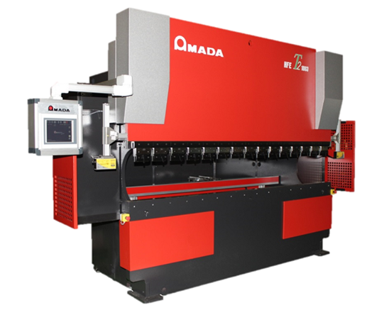
Figure 3. Modern bending press with CNC control
| Bending benchAmada HFE T2 |
Table 1. Technological possibilities of the device
| Q.nr | Technical parameter | Value |
| 1 | Bending force | 1000 kN |
| 2 | Distance between upper and lower beam in open position | 470 mm |
| 3 | Workflow | 200 mm |
| 4 | Approach speed | 100 mm/sec |
| 5 | Max. Working speed | 10 mm/sec |
| 6 | Max. ascent speed | 100 mm/sec |
| 7 | Number of axles | 4 |
| 8 | *- the detail can be positioned 590 mm to the extent that | 590 mm |
Undoubtedly, the width of the sheet, which fits between the columns of the bending press, is also important, and the maximum dimensions of the product to be manufactured are also derived from it.
For larger production volumes, it is expedient to automate the bending workplace. A complete automation solution is provided by integrating the bending press with the robot into one complete module. As an example, Figure 4 shows an integrated production module with an Amada HG-Rm bending robot. For larger production volumes, a definite trend is the use of production modules (see, for example, Figure 4), which are used as separate modules or directly connected to the production line. For production with a wide nomenclature and small batches, the most common option is to use separate production modules. To ensure higher productivity, such modules are integrated with automated material warehousing and sometimes automated packaging and warehousing solutions. The bending module integrated with the robot is shown in Figure 4.
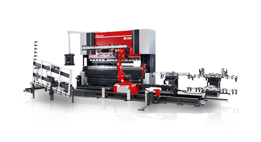
The HG-Rm production module is designed for the automatic bending of medium and large parts, where the bending process is time-consuming and requires considerable effort on the part of the operator, especially for heavy parts where two operators are used. The solution based on the HG-1303 model uses hybrid technology and an extremely robust design to meet the increased demands of production. The bending press is connected to a 7-axis robot and a number of smart devices that facilitate the bending of complex products and large panels.
Table 2 Module technical parameters
| Bending force | 1300 kN |
| The length of the worktable | 3110 mm |
| Distance between upper and lower beam in open position | 520 mm |
| Workflow | 250 mm |
| Approach speed | 220 mm/sec |
| Max. operating speed | 25 mm/sec |
| Max. ascent speed | 250 mm/sec |
| Control system | Amada 3i |
| Accessory | BI-S bending indicator |
| Number of robot axes | 6 + 1 axis on the rail |
| Robot rail length | 8 m / 4.8 m |
| Robotic lifting capacity | 80 kg (with grip) |
| Detail size | 100 x 500 until1250 x 2500 mm (thickness 0.5 – 6 mm) |
| Types of grippers | With suction cups/ Mechanical/ Combined |
| Loading details | 1 loading area |
| Unloading details | 2 position (basis) |
4.3 Press-brake machine construction principles and technological capabilities
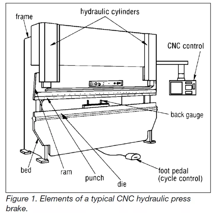
Press brakes are usually in the capacity range of 20 to 200 tons with bed lengths ranging from 4 to 14 feet (1.2 m to 4.3 m). They may be powered by mechanical, hydraulic or mechanical-hydraulic means. They may be “up- acting” or “down-acting,” depending on the direction of the ram’s power stroke. Figure 1 shows a down-acting CNC hydraulic press brake.
Press brakes may be equipped with one of several types of back gauges, including manually placed and adjusted gauges, pins which engage holes in the workpiece and computer numerically controlled programmable units which adjust settings after each stroke.
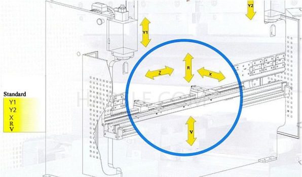
The axes’ orientation is best observed from the front of the press brake as shown below. The X-axis positions the gauge bar for the desired flange lengths. The R-axis controls the height of the gauge bar so the gauging surface can be positioned as needed. The Y-axis controls the stopping point of the press brake’s ram for the desired bend to occur. For hydraulic downacting press brakes, the Y-axis can also control the ram’s opening height and speed change point.
Machine details
Bending force – declared bending force for the press brake as the max. obtained force for the bend. Bending force is calculated according to the thickness of the part, material and bend requirements.
Bending length – declared bending length as the length of the table and the max. possible length for the tooling installation. Bending length usually shows the possibility of length to be bend with the press brake. Bending length could be standard (usually declared) or inside the columns (which the same as the distance between the columns) for the parts which require the deep positioning inside the throat.
Moveable beam, traverse – normally top beam of the machine which is moved together with the punch towards to the die to perform the bend. Beam has the controlled move with the hydraulic or electric systems.
Stroke of the press brake – declared stroke of the beam to move from the top position. Stroke of the bend together with the details and sizes of the punch and the die are necessary for the study of the bend possibilities.
Opening of the press brake, daylight – the max. possible distance from the top position of the beam and the bottom table without the installed tooling.
Back gauge of the press brake – back gauge is the main system at the rear part of the press-brake which is used as the stopper or fixation of the position of the part during the bending. Back gauge is the complex unit with the separate movements from manual to the servo-drived up to 6 moveable axis with CNC control for complex parts and programs.
Crowning, deflection – press brake because the construction has the internal structure deflections during the bend which are calculated and the subject for the elimination for the precision of the bend. Depends of the construction of the press brake the compensation of such deflections could be construction integrated, handwheel manual, hydraulic with CNC control etc.
Clamping, fixation of the tool – units and systems to clamp punches and dies with the beam and the table of the press brake. There are various systems of the tool clamping and fixation depends of the model and manufacturer, machine possibilities etc. Clamping is connected with the punch holder and die holder units as the middle part of the connection. In general clamping is the manual but could be replaced with pneumatic or hydraulic units.
Bending press construction
The bending press consists of a rigid frame that supports all components of the device. The high rigidity of the frame is important to avoid deformations in the structure that could affect the bending accuracy. When viewed from above, the top beam and bottom beam of the device are visible. One of the beams is vertically movable to exert the necessary bending force on the part placed between the die and the stamp.If the lower beam is movable, it is a so-called low-acting bending press and the upper beam is a high-performance bending press. Most modern bending machines are overactive, ie they move under the upper beam during the bending operation.
Basic parts of the bending press
The frame consists of a top beam (5) made of thick material, a bottom beam (6), side plates (1 and 1 ‘), an upper connecting beam (3) and support plates (2) on which the bending machine rests. C-shaped cut-outs are made in the side plates, which allow to increase the length of the bendable parts (the distance between the side plates is usually less than the length of the top and bottom beams).Since the upper beam is attached only at the ends, the upper and lower beams bend in opposite directions during bending. As a result, less stamping penetrates the die in thecenter of the work zone and the required bending angle cannot be achieved there.
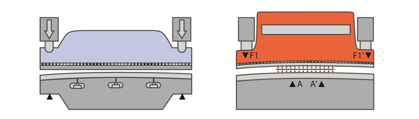
Lower and upper beam deflection
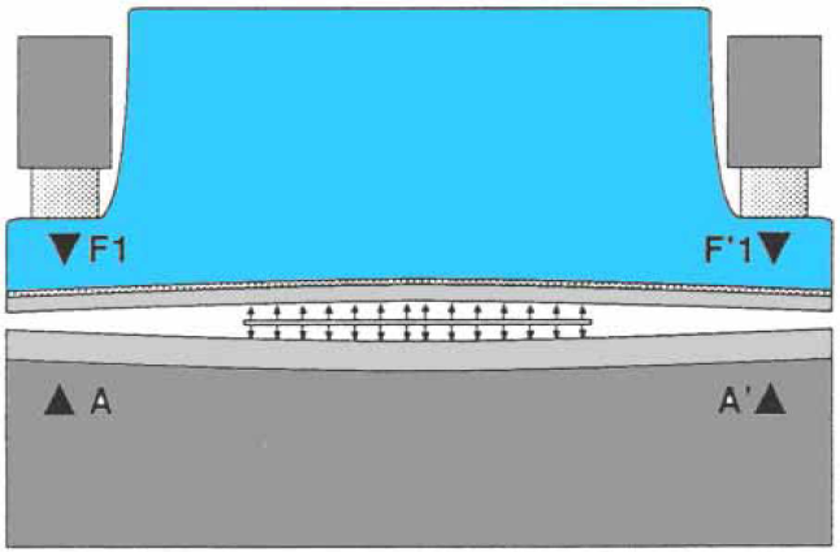
To eliminate this problem, hydraulic cylinders are installed in the middle part of the lower beam, which provide back pressure. The required back pressure (see figure) on CNC bending machines is calculated automatically. Another solution to this problem is to support the lower part of the lower beam (lower figure, points A and A ‘) and not to fasten the ends of the lower beam (so-called elastic lower beam). In this case, the lower beam follows the shape of the upper beam. The product stays straight because the bending is so small that the elasticity of the material is not exceeded – after removing the force, the product restores its straightness.
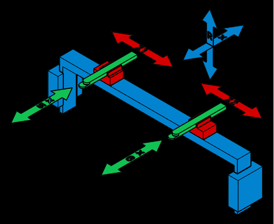
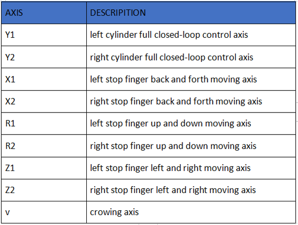
4.4 Control axes of the press-brake machine
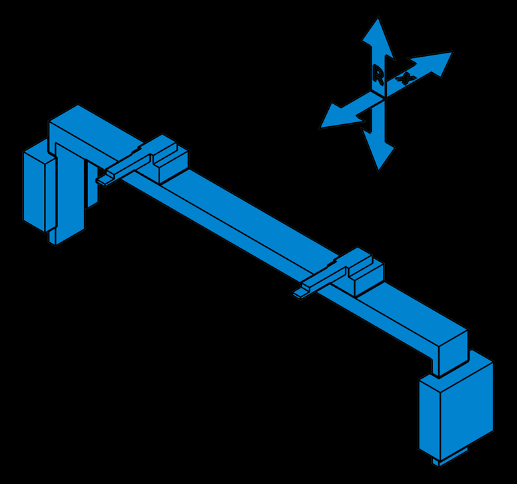
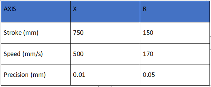
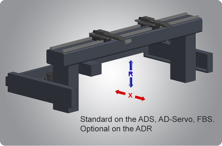
The basics: X-R axes
A press brake is equipped with a back gauge, a motorized structure to which backstops (also called “fingers”) are attached. By resting the metal sheet to the fingers, we determine the bending line. Movement of the back gauge along the machine depth (i.e. perpendicular to the ram) is called X axis. Vertical movement is called R axis, and is useful when we have profiles with multiple bends.
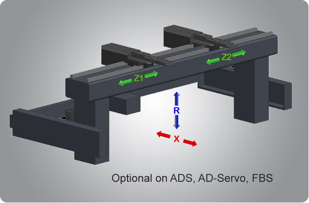
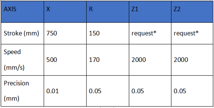
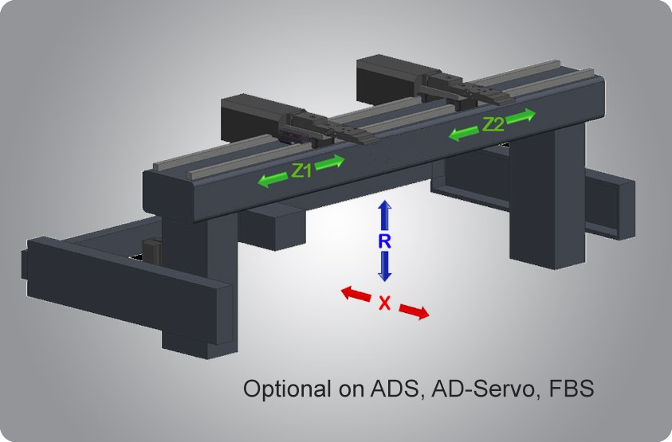
Working with bending stations or different lengths: Z1-Z2 axes
Working with bending stations or different lengths: Z1-Z2 axesBack gauge fingers are at least 2 in order to keep the piece in position. Their repositioning is usually manual, but can be motorized to facilitate working with bending statons or with pieces of different lengths. Movement is along the Z axis (parallel to the bending line), hence each of the backstops is named Z1, Z2, etc.
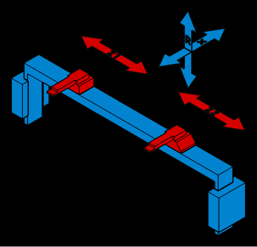
With Z1-Z2 axes we can only bend parallel to the backstop fingers. In order to make conical bends we need to bring one of the fingers closer or farther to the bending line, that is along the X axis. We can either use a manual movement, or a CNC-controlled motorized positioning. Axes are called X5 and X6. With just one motorized backstop we can make tapered bends up to 75°; with both axes we reach 80°. X5-X6 axes are useful also if you have sheet edges at different depths.
Conical bends or edges with different depths: X5-X6 axes
With Z1-Z2 axes we can only bend parallel to the backstop fingers. In order to make conical bends we need to bring one of the fingers closer or farther to the bending line, that is along the X axis. We can either use a manual movement, or a CNC-controlled motorized positioning. Axes are called X5 and X6. With just one motorized backstop we can make tapered bends up to 75°; with both axes we reach 80°. X5-X6 axes are useful also if you have sheet edges at different depths.
With Z1-Z2 axes we can only bend parallel to the backstop fingers. In order to make conical bends we need to bring one of the fingers closer or farther to the bending line, that is along the X axis. We can either use a manual movement, or a CNC-controlled motorized positioning. Axes are called X5 and X6. With just one motorized backstop we can make tapered bends up to 75°; with both axes we reach 80°. X5-X6 axes are useful also if you have sheet edges at different depths.
AXIS explanation
1 AXIS BACK GAUGE (based on MAZAKPOWER)
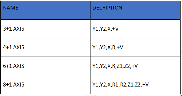
When we come to 1 axis back gauge, actually we mean 3+1 axis,1 axis back gauge is X axis. MAZAKPOWER press brake are provided are equipped with BGA-1 CNC back gauge constituted by a solid structure in order to assure the best repetitiveness and high precision in axes. For positioning X -axis the press is equipped with HIWIN linear guide and ball screw. In additional, there is equipped Z-axis with manual linear guide. Fingers can be moved manually and fixed in desired place. Z1, Z2 axis are adjusted manually and can be fixed in place. The single axis X-axis back gauge drives by the DELTA servo motor which controls the finger depth (flange depth).

2 AXIS BACK GAUGE
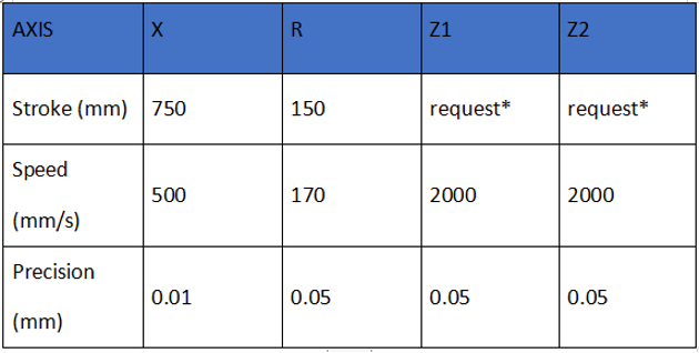
Also 2 axis back gauge (BGA-2) the X, R-axis are used. MAZAKPOWER fast and precise 2-axis CNC controlled back gauge that automatically adjusts the X (depth) and R (height) axes to ensure the material is always positioned accurately, resulting in higher quality finished parts. Axis movements are driven by AC motors and drivers. Using the best components, such as HIWIN (TAIWAN) ball screws, the back gauge movements are fast and precise, with X-axis speeds up to 500 mm/sec and stroke to 750 mm. high accuracy up to 0.01 mm.
4 AXIS BACK GAUGE4 Axis CNC back gauge (X-R-Z1-Z2), means 6+1 axis CNC press brake usually equipped with DELEM DA58T 2D graphical controller with PC-Profile-T2D software. Y1, Y2 precision ram positioning, X, R precision servo-driven back gauge drives by servo motor.
6 AXIS BACK GAUGE
6 Axis CNC back gauge (X1-X2-R1-R2-Z1-Z2), means 8+1 axis CNC press brake usually equipped with DA66T Touch 3D graphical control, auto crowning deflection compensation, the 6-axis back gauge offers you the highest degree of flexibility with highest production speeds. All 6 axis can be positioned independently of each other. Fingers can be independently located three dimension (X,R,Z) in the space. Control unit calculate finger positions on each axis. Stable finger position for asymmetrical work pieces, no setup times for back gauge adjustment.